Ring-O-Star
For somewhat obvious reasons my newest creation is called Ring-O-Star. Younger people may not quite get the association with a famous musician, but so be it 😉
I’ll write a technical article later, so here are some photos and videos of the real thing.


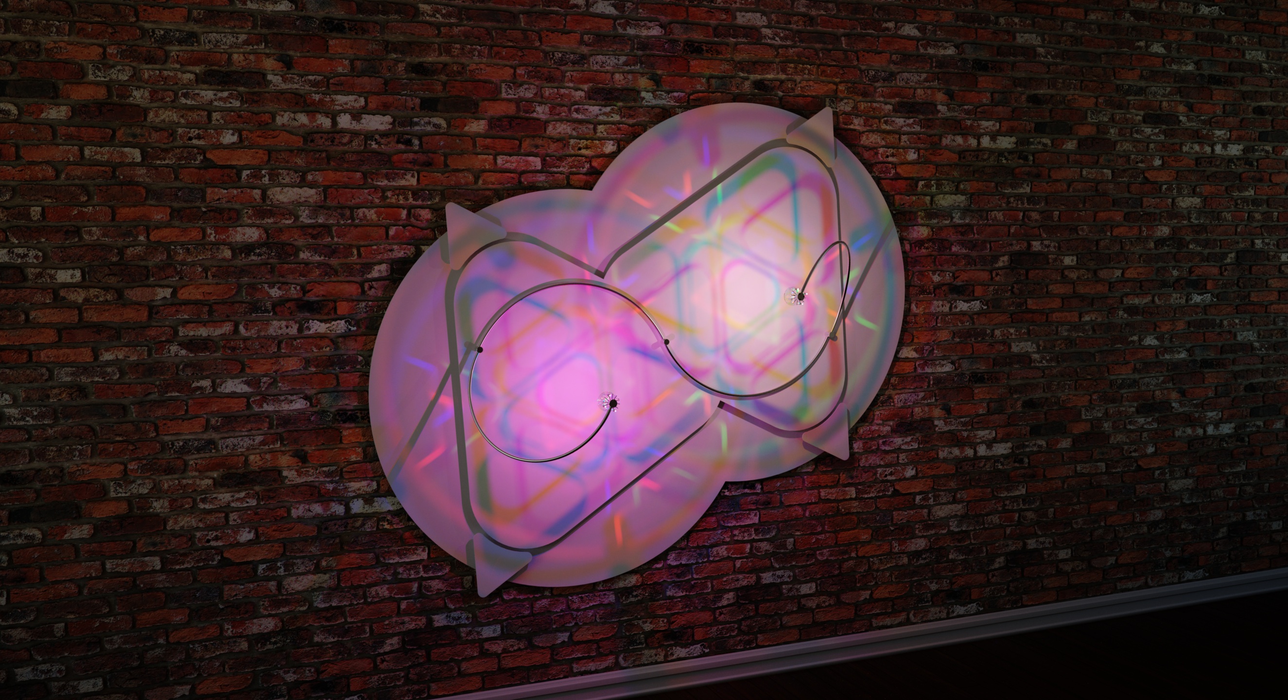
Rendering and Reality
Below are a computer rendering and a photo of my newest creation, soon to be installed in the Autodesk Inc. offices on Lake Oswego in Oregon.
I extensively use the CAD Software Fusion 360 for my designs and use the open source 3D software Blender and the commercial render engine Indigo Renderer to help design these objects. I’ve worked with CAD, computer graphics and rendering software for almost 25 years, but it still fascinates me how close the computer simulation and the photo are.
I’ve made no attempts to get these as close as possible and there is nothing calibrated in my workflow. The render comes out of Indigo Renderer without any post processing and the photo is straight off an iPhone 6. Mind-blowing, really!


3rd Prototype
I built another prototype with the 3D printed LED arms shown in the last post and made a few photos and a little video of it in action.

Enter 3D printing
I am a mechatronics engineer by trade and for most of the last 25 years have been involved in one form or another in the design and manufacturing of automated manufacturing machinery. That means I’ve used a lot of Aluminum. I really like aluminum as a material!
The essential mechanical pieces in my bigger lighting systems are machined from this very versatile material. The intention was to also use it in the much smaller lamp design I described in my last post.
The difficulty was to get someone to quote making the low quantity of these simple parts. The company had I worked with before did not have any capacity this time or no interest in providing me with a quote. A friend who owns a machining company asked me during dinner why I would not make these out of plastic. I came up with some answer but I had to admit to myself that it really was not a good answer. Perhaps I was just uncomfortable with the thought.
The sample parts for the very first prototype were given to me by another friend and kindred maker spirit down the road who has a 3D printer. In his words that 3D printer is very old and he is looking to buy a more up-to date machine. I had no experience with 3D printing and did not expect much. The ABS plastic parts that he gave me, while not very attractive visually, were much more mechanically sound than I had expected. They even took a small M3 thread well to hold some short set screws. These part have proven to be invaluable to debug the first prototype, have taken quite a beating, but they are still happily in service!
Based on that positive experience and out of pure curiosity I started browsing online 3D printing companies Shapeways, iMaterialize and Skulpteo and read forum posts on these sites to see what materials were available, what their limits would be, what sizes and finishes one could print in. The idea emerged to print not only the end and connecting pieces of an LED arm, but to 3D print the entire LED arm in one piece. This would not only open entirely new design options but would also help solve several challenges. Also, fewer parts means less time spend assembling and adjusting components.
The image below shows a computer rendering and lighting simulation of the re-designed lighting system with 3D printed LED arms. And the three photos that follow are closeup shots of the first set of 3D printed parts, which turned out to be absolutely phenomenal. Any surface imperfections that may be perceived in the photos are exaggerated by the magnification and the fact that I increased the sharpness of these images to possibly highlight any such imperfections. To the naked eye and touch these parts look and feel beautiful:


New small Lamp design
After installing the lamp as described in the last post I had a couple more leads for people or organizations interested in my work. One is a project in progress and I hope to deliver it to Lake Oswego in Oregon within the next two months.
The other lead was an intern at my current place of employment. I showed him some photos and this blog. Shortly before he left the company to go back to the university he indicated wanting to purchase one of my lamps.
What I’ve built so far are hand crafted, unique pieces and usually a bit out of reach for the average student so I crunched some numbers and designed a concept that was simpler mechanically and electronically without the ability to control it through an iPhone. The price I quoted was certainly one reason the deal did not work out.
However, what really turned out to be a problem I did not quite expect was the size of what I had quoted. While I had shrunk down the design by about 30% in size it was still way to big for example to be use a a desk lamp. I don’t think my young friend had the chance to observe one in person, and I believe he was really not aware of how big these are.
But I did decided to start investigating whether it was possible to find proper LEDs. The choice of available candidates is actually rather thin but sites like mouser.com offer great search tools to find what one needs. I had anticipated a long painful process but very quickly found some ideal candidates. At least ideal on paper specification. These have a forward current of max 200mA so are right between the usual small signal light LEDs and high brightness LEDs with 20-50 mA on the lower end and the High power LEDs starting at 350mA.
The light output was one concern. High power LEDs would have been too strong – that could have been managed – but also the size of the actual emitting surface needed to be as small as possible in order to create somewhat crisp patterns on the diffuse reflecting disks. So that fortunately worked out.
The next question that needed to be answered is of course how to drive these LEDs. An expensive constant current SMPS as used in my big systems was out of questions. Too big, too many components, too expensive for a smaller lower cost version. But here I got very luck a second time. Over the years I’ve collected some reference material about different LED drivers and just scrolling through one of the PDF files on my harddrive I found the CAT4109 from Onsemi that proved to be an ideal candidate as well. This is a very fast, linear, 3 channel constant current LED driver chip. Aside from being fairly inexpensive only 4 external components are needed. 3 resistors to set the desired constant current per channel and a decoupling capacitor that is almost unfair to count 😉
That pairs ideally with a Teensy LC micro-contoller board, which has 10 high resolution (up to 16 bit) PWM pins, of which I use 7 in this application.
I quickly set to design prototype PCBs, one carrying the three LEDs and one for the Microcontroller and LED driver chips. Actually it’s more of a feasibility study to see if it would actually work. I need to find out quickly whether the LEDs would create enough light and the light distribution was acceptable without undesirable artifacts. Naturally I also wanted to see if this setup could fade as smoothly as my bigger systems.
The image below may not look like much but this feasibility study proved very successful. This has been sitting in my living room and the LEDs have been fading and changing colors buttery smooth almost non-stop for the last 4 weeks:

So over the last 4-5 weeks I’ve gone ahead and designed a new lamp in Fusion 360:
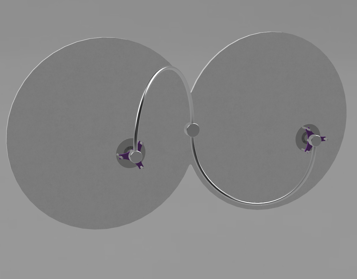
It looks simple but that’s been quite a challenge given the small scale of the components. The diameter of the machined parts is smaller than my index finger, yet I need to route 7 little insulated wires through the small piece without electrical shorts and while still keeping the overall system manufacturable by hand. The overall width of the system in the image above is a little less than my 27″ iMac is wide.
Here is an image of the machined component – here 3D printed in ABS – that is part of one of the two LED heads:

Here are images of the PCBs I created in Altium’s Circuit Maker :

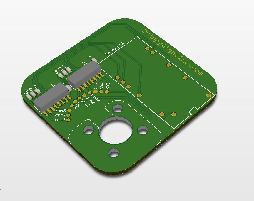
The machined part are out for quote. The PCB’s will go to OSH park so these will come back in a beautiful dark purple color. Aside from being functional I also wanted these to be “good looking” so I created a decorative pattern on the visible back face.
Hopefully I’ll be able to assemble some real prototypes within the next 4-6 weeks.
Imagery Sells
I’ve recently been presented with an opportunity to showcase my LED artwork in the iStore. The store had been around for a while and I had contemplated for some time asking whether they’d be interested of showcasing the Apple themed LED system I had designed.
The store had previously been located in downtown Greenville but in January they moved into another location into a brand new building on on One City Plaza in the center of downtown Greenville.
Then, in late January Apple started a new Ad campaign with the slogan “start something new” showcasing digital artwork created exclusively on Apple devices. That immediately clicked with me as I engineer my artwork – and there is a of lot of engineering in those lighting objects – exclusively on an iMac. However, while my artwork is also digital in many ways it’s distinctively different from the art displayed on the Apple web page.
When I turn all my apple devices off, my artwork is still there!
With that in mind I posted something on their Facebook site and ended up changing a number of emails with the store owner. Initially the idea was to install the Apple lamp pictured earlier in this blog but that did not work out. The store owner contacted his representative at Apple and she contacted the national Apple rep. The feedback was that the Apple logo cannot be used the way I used it. One of Steve Jobs often repeated quotes that Jobs attributed to Salvadore Dali is “Good Artists copy. Great Artists steal”. Dali apparently never made that quote but that did not prevent me from shamelessly stealing the Apple logo for my purpose and make it my own. Being aware of that it was still rather disappointing that we weren’t able to put that system in the store.
But I made one more attempt and asked the store owner whether he would be interested in showcasing one of my other designs. His response was that, yes, if I would be amenable to install this on the large headwall in his store. This head wall is a 30ft wide, 12 ft high, flat white painted perfect playground in a prime location. I was very amenable!
Here is a computer rendered (synthetic) image created with Blender and Indigo Renderer that simulates how it would look installed in the store:

These next two photograph were taken with an iPhone 6 and show the system as installed in the store:
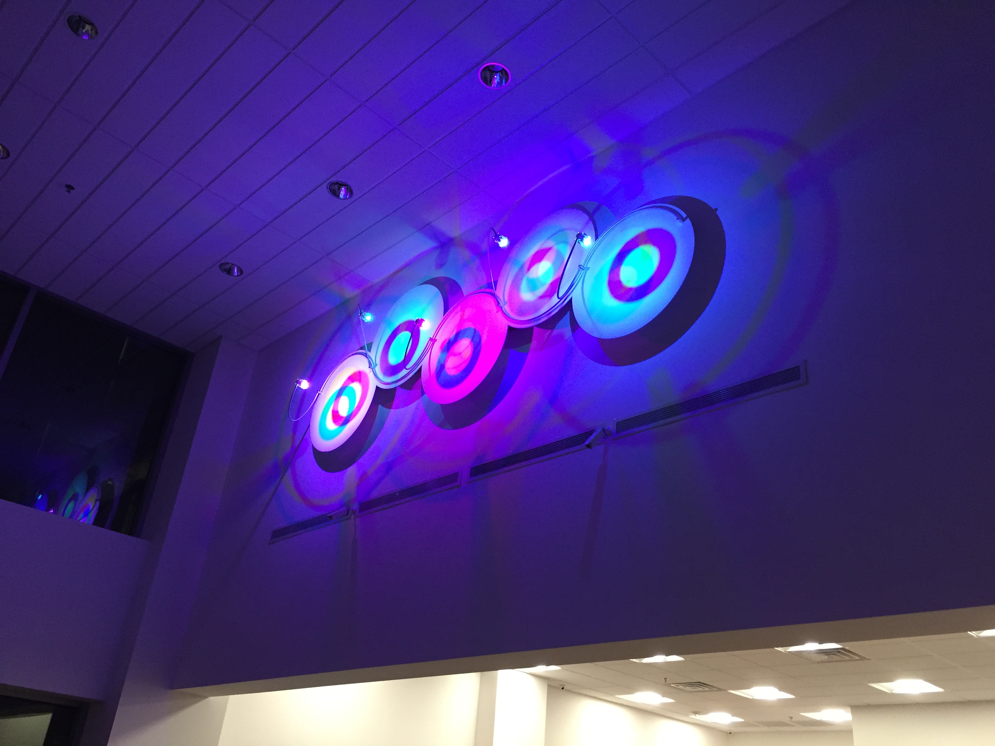

These images were taken on the night of the installation. When we walked out of the store to see how it would look from the outside the store owner told me that the series of renderings I’d prepared were what sold him on the idea.
Update to the Arduino Eclipse IDE/Plugin installation instructions
I recently updated my own toolchain to the newest versions of all involved software:
- Arduino 1.0.6
- Teensyduino 1.20 plugin installed into Arduino 1.0.6
- Arduino 1.5.8
- Eclipse Arduino IDE 2.4
The instructions still work as written, however, for users of the Teensy 3.x boards the boards txt file had to be updated to allow the selections for the Teensy 3.1 under clocking for low power applications. The overlocking speeds are commented out, but are easy to enable by editing the boards.txt.
Arduino Eclipse Plugin – Other Resources
I have added a new menu entry in the Arduino Eclipse Plugin section called Other Resources
This should help when questions arise that I cannot answer. Many questions can be answered on the Arduino forum thread for the Plugin. Should you find a bug or unusual behavior of the plugin it may be a good idea to open a new issue on the GitHub site for the plugin.
The third link (so far) is to a blog post that is written by an experienced programmer and explains very nicely why one would use the Plugin over the Arduino IDE.
Last but not least I have discovered on my own iPad that selecting the Wordpress submenus is very cumbersome. Now when selecting the Arduino Eclipse Plugin menu entry the resulting page contains the links to the sub-pages that can normally be reached by using the menu.
TouchOSC Arduino Tutorial
I’ve added a little Tutorial that describes in detail how to send and receive OSC (Open Sound Control) messages with an Arduino Sketch
There are a number of tutorials and resources on the Internet that show how to do this this but the one’s I found leave to be desired in one or the other area.
- This tutorial does not require a “middle man” e.g. a PC or other computer to receive and interpret OSC messages via Processing and then send commands to the remote device. The Arduino exchanges OSC messages directly with the device to be remotely controlled.
- Some tutorials use old and non-maintained Arduino OSC libraries such as ArdOSC or zOSC. This tutorial uses the Oscuino library, which is written and actively maitained by the inventors o the OSC protocol at CNMAT Center for New Music & Audio technology
A feature of TouchOSC that AFAIK only works on iOS devices is that it can recognize devices that have registered an OSC service on the local network by using Apples implementation of ZeroConf networking called Bonjour. In a next tutorial I will show how to accomplish that using the Arduino Bonjour library.
The most reliable hardware combination I’ve found to do this with is a Teensy 3.0 (or 3.1) connected to a WIZ820io embedded Ethernet module that is connected to a Pocket WiFi Router such as the TP-Link TL WR702n (Or 703n). While this is certainly more bulky than a solution that employs one of the available WiFi modules such as the TI CC3000 it has a few significant advantages.
- The TP Link WiFi router comes out-of-the-box in AP (Access Point) mode and that makes it very easy to connect to the Microcontroller directly without having to integrate it into an existing TCP/IP network. Great for debugging communications! I am not currenty aware of any of the IoT WiFi modules that can work as an AP.
- Once a project is debugged and UDP packages and OSC messages are exchanged the router can be connected to an existing network an this is quickly done through an easy to use web interface.
- The WIZ820io uses a Wiznet W5200 Ethernet Chip that also supports Multicast DNS. That is a prerequisite for Bonjour to work. I’ve not been able to find an embedded WiFi module that fully supports this. The very new Texas Instruments CC3100 may be the first one. I believe it when I see it.
However, when Bonjour functionality is not required, then this may actually work fine on a SparkCore. The above suggested hardware does work – including Bonjour – as I use it successfully in my LED Lighting Systems
Finishing touches on mechanical design
The prototypes built so far look finished from the front, which was very intentional. People that have stepped into my living room have unanimously found my creations beautiful. However there still was so much to be done on packaging the electronics and integrating everything nicely so it would look…well, finished like a intentional product. Done!
Another problem which solution I had deferred was how to be able to break a lamp down so it would be shippable. That of course would require some form of reassembly and the intention was for that not to be more complicated than say a simple IKEA chair. This was a real challenge as this also needed to include a safe and solid electrical interconnect. Fortunately a good idea hit unexpectedly and hopefully within the next 3-4 weeks I have prototype parts on hand to see if the idea works as well in hardware as it works on computer screen.
Should things work as planned the goal is to have three fully functional prototypes assembled this year and perhaps until then the search for an avenue to exhibit these presents itself. Two these prototypes have been part of previous posts. The third one is an almost three year old design that hopefully will take shape over the next few months.
Endor Star