New small Lamp design
After installing the lamp as described in the last post I had a couple more leads for people or organizations interested in my work. One is a project in progress and I hope to deliver it to Lake Oswego in Oregon within the next two months.
The other lead was an intern at my current place of employment. I showed him some photos and this blog. Shortly before he left the company to go back to the university he indicated wanting to purchase one of my lamps.
What I’ve built so far are hand crafted, unique pieces and usually a bit out of reach for the average student so I crunched some numbers and designed a concept that was simpler mechanically and electronically without the ability to control it through an iPhone. The price I quoted was certainly one reason the deal did not work out.
However, what really turned out to be a problem I did not quite expect was the size of what I had quoted. While I had shrunk down the design by about 30% in size it was still way to big for example to be use a a desk lamp. I don’t think my young friend had the chance to observe one in person, and I believe he was really not aware of how big these are.
But I did decided to start investigating whether it was possible to find proper LEDs. The choice of available candidates is actually rather thin but sites like mouser.com offer great search tools to find what one needs. I had anticipated a long painful process but very quickly found some ideal candidates. At least ideal on paper specification. These have a forward current of max 200mA so are right between the usual small signal light LEDs and high brightness LEDs with 20-50 mA on the lower end and the High power LEDs starting at 350mA.
The light output was one concern. High power LEDs would have been too strong – that could have been managed – but also the size of the actual emitting surface needed to be as small as possible in order to create somewhat crisp patterns on the diffuse reflecting disks. So that fortunately worked out.
The next question that needed to be answered is of course how to drive these LEDs. An expensive constant current SMPS as used in my big systems was out of questions. Too big, too many components, too expensive for a smaller lower cost version. But here I got very luck a second time. Over the years I’ve collected some reference material about different LED drivers and just scrolling through one of the PDF files on my harddrive I found the CAT4109 from Onsemi that proved to be an ideal candidate as well. This is a very fast, linear, 3 channel constant current LED driver chip. Aside from being fairly inexpensive only 4 external components are needed. 3 resistors to set the desired constant current per channel and a decoupling capacitor that is almost unfair to count 😉
That pairs ideally with a Teensy LC micro-contoller board, which has 10 high resolution (up to 16 bit) PWM pins, of which I use 7 in this application.
I quickly set to design prototype PCBs, one carrying the three LEDs and one for the Microcontroller and LED driver chips. Actually it’s more of a feasibility study to see if it would actually work. I need to find out quickly whether the LEDs would create enough light and the light distribution was acceptable without undesirable artifacts. Naturally I also wanted to see if this setup could fade as smoothly as my bigger systems.
The image below may not look like much but this feasibility study proved very successful. This has been sitting in my living room and the LEDs have been fading and changing colors buttery smooth almost non-stop for the last 4 weeks:

So over the last 4-5 weeks I’ve gone ahead and designed a new lamp in Fusion 360:
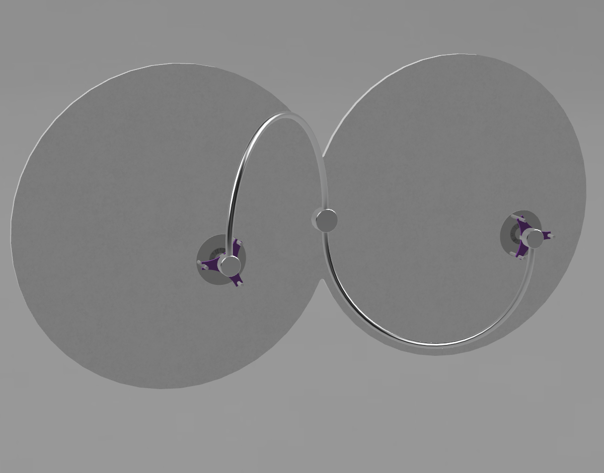
It looks simple but that’s been quite a challenge given the small scale of the components. The diameter of the machined parts is smaller than my index finger, yet I need to route 7 little insulated wires through the small piece without electrical shorts and while still keeping the overall system manufacturable by hand. The overall width of the system in the image above is a little less than my 27″ iMac is wide.
Here is an image of the machined component – here 3D printed in ABS – that is part of one of the two LED heads:

Here are images of the PCBs I created in Altium’s Circuit Maker :

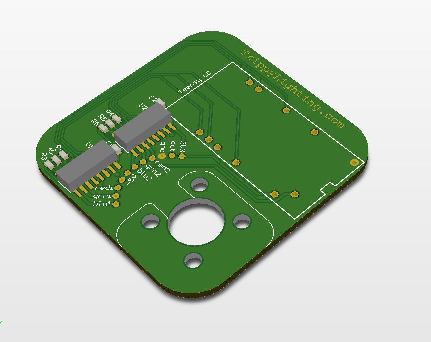
The machined part are out for quote. The PCB’s will go to OSH park so these will come back in a beautiful dark purple color. Aside from being functional I also wanted these to be “good looking” so I created a decorative pattern on the visible back face.
Hopefully I’ll be able to assemble some real prototypes within the next 4-6 weeks.
Posted on November 4, 2015, in Uncategorized. Bookmark the permalink. Leave a comment.


Leave a comment
Comments 0