TouchOSC and OSCuino
This little tutorial describes how to control an Arduino with TouchOSC.
Prerequisites:
- Hardware:
- Arduino Board. This was tested with an Arduino Uno, and a Teensy 3
- Arduino Ethernet Shield. There are several clones of the original shield available in different price ranges. As long as these host a W5100 or W5200 Ethernet chip it should work. A word of caution: the standard Arduino Ethernet library does not support the W5200 Ethernet Chip so if you want to use a clone with a W5200, make sure it’s supported with a version of the Ethernet library. The Seeed Studio Ethernet Shield V2.0 for example hosts the W5200 Ethernet Chip and comes with it’s own version of the Ethernet Library that supports the W5200 chip. This has been tested with an original Arduino Ethernet Shield on an Arduino Uno and with the WIZ820io Ethernet Module in conjunction with a Teensy 3
- Optional:
If a WiFi solution is desired the simplest solution is to connect a little pocket WiFi router such as the TP-Link TL-WR702n or TL-MR3020 to the Ethernet shield or module. The web interface that is used to configure these routers is in English. The TL-WR703n that is also available cheaply on eBay has a more capable processor and is popular amongst people that want to run the Linux based Open-WRT router software on the little router. However, out-of-the-box the interface is in Chinese. I’ve persevered through the Chinese and have worked successfully with the 703n as well as the 702n.
A note of caution: In the section below “What’s left to do” I mention that this setup also can be made work nicely in conjunction with Apple’s Bonjour. This only works with these two little routers with the original firmware. Open-WRT is Linux based and does not support Bonjour out-of-the-box. Installing Avahi – the Linux implementation of ZeroConf Networking requires more memory than these small routers have. It may be possible to get this to work, but I have decided to use my limited time for something else 😉 - Optional:
This should also work nicely with a Sparkcore. I did some quick and admittedly sloppy research and I believe based on this Sparkcore Forum post that the Oscuino library has been successfully ported to also run on the Sparkcore. However, the Texas instruments CC3000 WiFi Chip/Module that is utilized the Sparkcore only implements a very rudimentary subset of multicast DNS (mDNS). This does not allow for service registration. As such Bonjour also will not work with this setup. OSC messages OTOH should work fine and this would be a physically very small solution!
- Software:
- Oscuino, the Arduino OSC library. This is recommended over any other Arduino OSC implementations such as ArdOSC Z-OSC etc. Oscuino is the most complete implementation of the OSC protocol and is written and actively maintained by the inventors of the OSC protocol at the CNMAT | The Center for New Musik and Audio technology and the University of California at Berkley
- Arduino 1.0.5 IDE or higher. Tested with Arduino 1.0.5.
- Teensyduino if you are working with a Teensy.
- TouchOSC and the TouchOSC editor for your operating system. Tested on Mac OSX and iPhone 4 & 6. It’s available for Android as well.
The complete Arduino sketch and TouchOSC layout can be downloaded from the GitHub repository.
Lets start with the TouchOSC layout.
The first thing that needs to be done is to move the layout from your file explorer to your mobile device. There are two ways to achieve this. One includes transfer over WiFi while the other involves iTunes.
We’ll use the Layout transfer over WiFi, which requires the TouchOSC editor to be installed on your computer. This is an application written in Java and needs a Java run time engine on your computer. Mac OSX comes pre-installed with one so this will not be discussed here. Follow the online instructions and transfer the layout that you downloaded from the Github repository to your mobile device.
The layout has two pages, one with a simple button and one with a fader. Both of these controls will send OSC messages to the Arduino. The Arduino will send a message back to the controls and the Controls will respond to these messages.
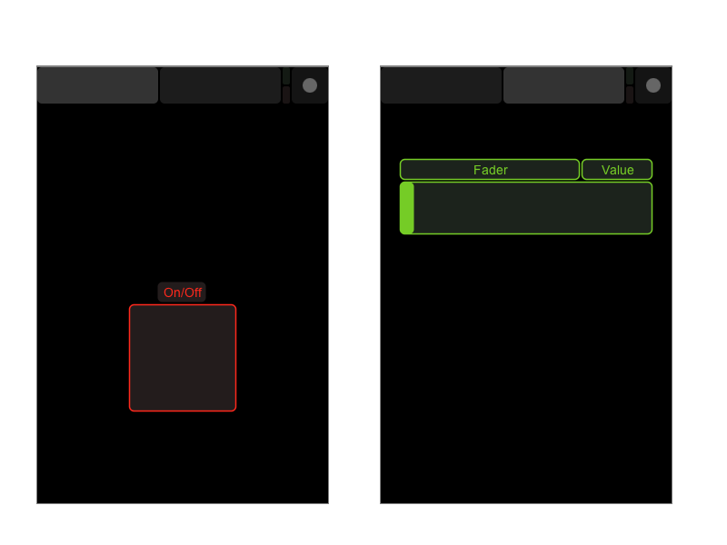
The Button
When the button is pressed it will send an OSC message to the Arduino Sketch to turn on the LED on the Arduino board and to print a message in the Arduino IDE Serial Monitor. The sketch will then send a message back to the control that turns the inside field on the button red to indicate that indeed the message has been received, a message has been printed and the LED is on. When designing your own controls it is important to note that for this toggle button to respond to OSC messages “Local feedback off” bust be checked in the editing properties in the TouchOSC Editor.
The Fader
When the Fader is moved it sends OSC messages corresponding to its position to the Arduino Sketch. The Arduino Sketch will receive the message and will print the value received with the message in the Serial Monitor. It wl also send an OSC message to the little label in the upper right corner above the fader. The label will display the value to which the slider has moved.
Arduino Sketch
Before we continue the Arduino Sketch a few details about the OSC protocol and TouchOSC need to be discussed. The OSC protocol communicates through OSC bundles and OSC messages. In simple terms a OSC bundle combines one, or more OSC messages and a time tag. Each OSC message can contain several values of different data types, such as integer, float, string and blob.
- TouchOSC only sends and receives OSC messages, not OSC bundles.
- TouchOSC only sends and receives values of the data type float
The complete sketch is listed in the scroll box at the very bottom of this page and can be copy/pasted into the Arduino IDE editor. The sketch uses DHCP to receive an IP address form a router, however by uncommenting a few lines a static IP can be assigned to the Arduino as well. For more details on how to create an Ethernet connection with the Arduino please refer to the Arduino online documentation.
Other than the
#include <OSCBundle.h>
There is nothing OSC specific in the Sketch until we come to :
void loop(){
  //process received messages
  OSCMsgReceive();
}
This runs only one function that receives UDP packets and parses these for OSC messages.
void OSCMsgReceive(){
  OSCMessage msgIN;
  int size;
  if((size = Udp.parsePacket())>0){
    while(size--)
      msgIN.fill(Udp.read());
    if(!msgIN.hasError()){
      msgIN.route("/OnOff/toggle1",toggleOnOff);
      msgIN.route("/Fader/Value",funcValue);
    }
  }
}
In detail it fills the inMsg instance of the OSCMessage object until the received UDP packet is empty. If the message has no error and matches one of the OSC addresses
"/OnOff/toggle1" or "/Fader/Value"
it routes to (executes) the assigned functions. So lets look at one of these:
void toggleOnOff(OSCMessage &msg, int addrOffset){
  ledState = (boolean) msg.getFloat(0);
  OSCMessage msgOUT("/OnOff/toggle1");

  digitalWrite(ledPin, ledState);

  msgOUT.add(ledState);
  if (ledState) {
    Serial.println("LED on");
  }
  else {
    Serial.println("LED off");
  }

  ledState = !ledState;		 // toggle the state from HIGH to LOW to HIGH to LOW ...

  //send osc message back to control object in TouchOSC
  //Local feedback is turned off in the TouchOSC interface.
  //The button is turned on in TouchOSC interface whe the conrol receives this message.
  Udp.beginPacket(Udp.remoteIP(), destPort);
  msgOUT.send(Udp); // send the bytes
  Udp.endPacket(); // mark the end of the OSC Packet
  msgOUT.empty(); // free space occupied by message
}
- First we read the value on position zero and assign it to the boolean variable ledState
- Then we create another OSCMessage object instance for an outgoing OSC message. This message only has an OSC address assigned but is otherwise empty.
- Then we turn the LED “on” on the Arduino.
- The next step fills the msgOUT object with the value of the LED state to be sent back to the TouchOSC button
- and then a few equivalent messages are printed to the Serial monitor.
- Then we toggle the LED state for the next go-around.
- The last 4 lines send the OSC message per UDP to the TouchOSC button.
The second OSC function is very similar and it should be easy to understand now.
Last steps before operating the TouchOSC controls
- After compiling and uploading the Sketch to your Arduino, turn on the Serial Monitor and wait until it prints the assigned IP
- Enter that IP address into the “Host” field in the Touch OSC connection configuration screen.
What’s left to do ?
The last steps exhibit one weakness. This works OK for a breadboard project, but once you have the project installed permanently and not connected to the Arduino IDE and its Serial Monitor it will be rather cumbersome to retrieve the IP address assigned to it, not to speak about it’s port settings . You can assign a static IP but that is also not such a great solution, particularly if you have more than one Arduino project. So what is a nice solution?
On iOS devices TouchOSC supports Apples implementation of ZeroConf configuration networking called Bonjour. If a device advertises/registers for example an OSC service, TouchOSC will discover that service and show it in its configuration screen. This will allow a device to receive an IP per DHCP and whatever IP and port setting the device advertises will be auto-configured by one touch on the TouchOSC interface. Now THAT is a nice solution!
It’s also relatively simple to do with the Arduino Ethernet Bonjour library. However, as that library consumes too much memory on an Arduino Uno it is recommended for boards with larger memory footprints such as the Teensy ++2 or Teensy 3. It should also work nicely on Arduino Mega’s etc. But we’l leave that for another tutorial…
//DHCP-based OSC server test code
//for use with IDE 1.0.5
//for use with W5100 or W5200 based ethernet shields

#include <SPI.h>
#include <Ethernet.h>
#include <EthernetUdp.h>
#include <OSCBundle.h>

// you can find this written on the board of some Arduino Ethernets or shields
byte mac[] = {
  0xDE, 0xAD, 0xBE, 0xEF, 0xFE, 0xED };

// NOTE: Alternatively, you can assign a fixed IP to configure your
//       Ethernet shield.
//       byte ip[] = { 192, 168, 0, 154 };


int serverPort  = 8000; //TouchOSC (incoming port)
int destPort = 9000;    //TouchOSC (outgoing port)
int ledPin =  13;       //pin 13 on Arduino Uno. Pin 6 on a Teensy++2
int ledState = LOW;

//Create UDP message object
EthernetUDP Udp;

void setup(){
  Serial.begin(9600); //9600 for a "normal" Arduino board (Uno for example). 115200 for a Teensy ++2
  Serial.println("OSC test");

  // start the Ethernet connection:
  // NOTE: Alternatively, you can assign a fixed IP to configure your
  //       Ethernet shield.
  //       Ethernet.begin(mac, ip);
  if (Ethernet.begin(mac) == 0) {
    Serial.println("Failed to configure Ethernet using DHCP");
    // no point in carrying on, so do nothing forevermore:
    while(true);
  }
  // print your local IP address:
  Serial.print("Arduino IP address: ");
  for (byte thisByte = 0; thisByte < 4; thisByte++) {
    // print the value of each byte of the IP address:
    Serial.print(Ethernet.localIP()[thisByte], DEC);
    Serial.print(".");
  }

  Udp.begin(serverPort);
}

void loop(){
  //process received messages
  OSCMsgReceive();
}

void OSCMsgReceive(){
  OSCMessage msgIN;
  int size;
  if((size = Udp.parsePacket())>0){
    while(size--)
      msgIN.fill(Udp.read());
    if(!msgIN.hasError()){
      msgIN.route("/OnOff/toggle1",toggleOnOff);
      msgIN.route("/Fader/Value",funcValue);
    }
  }
}

void toggleOnOff(OSCMessage &msg, int addrOffset){
  ledState = (boolean) msg.getFloat(0);
  OSCMessage msgOUT("/OnOff/toggle1");

  digitalWrite(ledPin, ledState);

  msgOUT.add(ledState);
  if (ledState) {
    Serial.println("LED on");
  }
  else {
    Serial.println("LED off");
  }

  ledState = !ledState;		 // toggle the state from HIGH to LOW to HIGH to LOW ...

  //send osc message back to controll object in TouchOSC
  //Local feedback is turned off in the TouchOSC interface.
  //The button is turned on in TouchOSC interface whe the conrol receives this message.
  Udp.beginPacket(Udp.remoteIP(), destPort);
  msgOUT.send(Udp); // send the bytes
  Udp.endPacket(); // mark the end of the OSC Packet
  msgOUT.empty(); // free space occupied by message
}

void funcValue(OSCMessage &msg, int addrOffset ){

  int value = msg.getFloat(0);
  OSCMessage msgOUT("/Fader/Value");

  Serial.print("Value = : ");
  Serial.println(value);

  msgOUT.add(value);

  Udp.beginPacket(Udp.remoteIP(), destPort);
  msgOUT.send(Udp); // send the bytes
  Udp.endPacket(); // mark the end of the OSC Packet
  msgOUT.empty(); // free space occupied by message
}


This was an awesome tutorial. Thank you. I had one hiccup. I noticed my pin was much dimmer than I expected. After some trouble shooting I found that the pin was outputting ~3V rather than 5V when in circuit. When I added:
pinMode(ledPin, OUTPUT);
to void setup(), my pin started outputting 5V as expected. Don’t know why, but I’m thrilled it works. Thank you for the guide. Super helpful.
Hi,
I am glad it worked for you! Thank you very much for the feedback, a that rarely happens!
Hi trippylighting, just wondering if you know how to pass the name of the OSC control as an argument to the function being called. msgIN.route(“/OnOff/toggle1”,toggleOnOff);
Would be something like msgIN.route(“/OnOff/toggle1”,doSomething “/OnOff/toggle1”);
void doSomething(OSCMessage &msg, int addrOffset, char controlName){
}
I am using the ardOSC library, so for me, I want to pass the control’s name when I do the server.addCallback().
Any hot tips appreciated. I posted on the Arduino forums too, but it’s a bit hard getting noticed over there these days.
http://forum.arduino.cc/index.php?topic=288704.0
Thanks.
Hi Carl,
Unfortunately I cannot help you with ardOSC. It’s certainly a neat little library, however, it is not actively maintained anymore and really only covers a small subset of what the OSC protocol has to offer. Also, if I remember correctly it was/ is hardware dependent and requires a W5100 chip.
That’s why I changed to use OSCuino. That OSC library is actively maintained by the inventors of the protocol. It is also not directly hardware dependent so for example if you want to use a WIZ820io Ethernt module with the much more capable W5200 chip then you can do that. It also has been ported to run on a spark core but I don’t have any experience with that board myself.
My recommendation for you would be to change from using ardOSC to OSCuino. When I started converting my own application to OSCuino there were no tutorials and it took some experimentation to get it to work. That’s why I wrote this little tutorial and while it only uses two controls, a button and a fader it covers all you need in that is sends and receives OSC messages.
If you have any problems with the little tutorial, please let me know.
Are you using ardOSC with TouchOSC ?
Hi and thanks for getting back to me so quickly! You’re Headroom, correct?
Yes, I am using TouchOSC with ardOSC. Is there something better than touchOSC? Something with a textbox that I could get feedback on the values of a control would be something I could really use. An XY color picker would be fabulous!
I am a little reluctant to change libraries as I sure struggled to get OSC/DMX/Ethernet all behaving, but I am going to give it a shot.
Would I be able to pass arguments withe the msgIN.route() statement -or- some way for the function being called to know which control is doing the calling? As I add lighting fixtures, especially when we’re getting into 6 elements per fixture (RGBWAUv) the code gets a bit unmanageable.
Have a great 2015,
Carl
Yes, thats my user name on the Arduino forum and a few others. To me the Arduino forum is not so particularly useful. The vast majority are new users that keep asking the same questions that have been answered a million times. If you need help beyond, things get a little thinner. When I started using Teensy boards, and after the Teensy 3 was introduced the support forum for the Teensy boards was also introduced and there are a number of users that really know how to program micro controllers.
You can display text/number values in TouchOSC that are send by your micro controller. It’s called a Label and thats actually exactly what the little demo program in my tutorial does. The second screen with the fader has a small “Value” field and when you move the slider it sends a value to the micro controller and the micro controller sends a value back that then is displayed.
If you want to kick it up a little notch you could look at Lemur I have not used it myself, but it does use more of the OSC functionality in that it also can sends OSC bundles and not just OSC messages. I believe that also is a limitation of ardOSC that it cannot deal with bundles. TouchOSC only send/receives OSC messages but no OSC bundles. However, Lemur is a bit more expensive than TouchOSC.
Also, you are mentioning DMX, Ethernet and OSC in one breath. I’d strongly recommend for you to take a look at the Teensy 3 or Teensy 3.1 board. The guys at CNMAT that invented the OSC protocol and the Oscuino library measured the highest throughput with the Teensy boards. Also the Ethernet library that comes installed with Teensyduino has an auto detect feature to detect a the W5200 chip for example on the WIZ820io Ethernet Module. The W5200 is much faster than the W5100. In fact I use a Teensy 3 and WIZ820io myself. Oh, and if you want to know how to have your Adruino to show up in the device configuration in TouchOSC per Bonjour that can be done as well!
I tried to convert my sketch over to the OSCuino library but there seems to be a conflict with the Conceptinetics DMX Shield library, the compile error is:
core.a(HardwareSerial.cpp.o): In function `__vector_18′:
D:\D_E_V\ARDUINO\arduino-1.0.5\hardware\arduino\cores\arduino/HardwareSerial.cpp:115: multiple definition of `__vector_18′
Conceptinetics\Conceptinetics.cpp.o:D:\D_E_V\ARDUINO\arduino-1.0.5\libraries\Conceptinetics/Conceptinetics.cpp:1162: first defined here
There is some info here: http://sourceforge.net/p/dmxlibraryforar/wiki/Compiling%20issues/
I took the DMX Master example sketch and tried adding the libraries I require:
#include
#include
#include
#include
#include
If I rem out the OSCBundle library, the thing compiles. Conversely, when I take your tutorial sketch and include the Conceptinetics library, it throws the same error. Any workarounds that you know of?
Thanks again
Hey! I’m rather proud that I figured it out by myself 🙂
In the OSC\readme I found this:
SLIPSerial
The OSC for Arduino library includes extensions of the USB serial and Hardware serial functions of the Arduino core that sends and receives data using the SLIP encoding.
This makes Max/MSP and PD integration very simple using CNMAT’s o.io.slipserial.
The SLIPSerial library implements the same methods as the Serial object with additional “beginPacket” and “endPacket” methods to
mark the boundaries of each packet in a serial stream.
So I removed Slip*.* from the OSC library folder (as it is not required for my project), restarted the IDE, and presto, no conflicts, yeah!
I am glad you figured it out and hope the little tutorial was helpful.
Hi Headroom:
Yes, your tutorial and encouragement was what I needed to migrate to the CNMATOSC library.
I am still trying to get around my original problem and that is passing the name of the TouchOSC control to the function that is being callled by the dispatcher msgIN.route().
I was looking into getAddress, believing I could get the name of the TouchOSC control from there, but I don’t seem to have much luck. The thing with TouchOSC is: I can getInt() to get the value of the control, but the other piece of information I require (DMX Channel) is identified by the naming convention I used when naming the controls, /1/fdr_RED_01 for example is DMX channel 1.
I am getting results from getAddress, but I don’t seem to be able to make any sense of it other than I can see the IP Address of my iPad.
Do you have any idea how I could get the name of the control into the function being called? In your example, I would like to pass “/Fader/Value” to funcValue.
Here’s the code for my attempt at using getAddress() to accomplish this.
http://theonqgroup.com/pub/getaddress_test.html
As always, your help is appreciated,
Carl
Sorry for the late reply.
I don’t think there is a way to to
But you can achieve the functionality you are looking for another way. You’ve already discovered that you can get the OSC message string with getAddress.
Look in OSCmessage.cpp. There are string matching functions that will allow you to parse the OSCaddress for a string pattern. In your case that would be either the “/1” or the “/fdr_RED_01”.
/*=============================================================================
	PATTERN MATCHING
=============================================================================*/

int OSCMessage::match(const  char * pattern, int addr_offset){
	int pattern_offset;
	int address_offset;
	int ret = osc_match(address + addr_offset, pattern, &pattern_offset, &address_offset);
	char * next = (char *) (address + addr_offset + pattern_offset);
	if (ret==3){
		return pattern_offset;
	} else if (pattern_offset > 0 && *next == '/'){
		return pattern_offset;
	} else {
		return 0;
	}
}

bool OSCMessage::fullMatch( const char * pattern, int addr_offset){
	int pattern_offset;
	int address_offset;
	int ret = osc_match(address + addr_offset, pattern, &address_offset, &pattern_offset);
	return (ret==3);
}
I have another bigger example sketch that I salvaged form the web before OSCuino was officially hosted on the CNMAT website.
It took me a while and is almost a complete re-write to make it work with the current form of OSCuino and works on a Teensy 3 board. What it does is demonstrated in this video:
The sketch demonstrates what I have tried to explain. As I work almost exclusively with the Arduino Eclipse IDE it’s not ready for publishing but I think I sent a copy to CNMAT that is ready for the Arduino IDE and also runs on a UNO. Let me know if that interests you.
Well I don’t like to be spoon fed, when I figure stuff out the hard way it tends to stick better, but starting to bang head on keyboard.
I’ve tried pattern matching, it seems most of the examples I’ve found have to do with sending messages, I “simply” need to know which TouchOSC control sent the message. It know it is included with the incoming OSC message, I just can’t figure out how to extract it.
I tried
if (msg.fullMatch(“/1”, addrOffset)){
Serial.println(“We’ve got a match!”);
}
but it never goes true. I tried testing for /1, /fdr_RED_01, /1/fdr_RED_01 but no luck. It must be there, as the msgIN.route() method does pattern matching to know which function to call.
My latest light fixtures have 10 DMX channels each, if I have to create a separate function for each channel, I will run out of program memory quite fast, as well as be a bear to maintain. There must be some way to do it with a single function you’d think. Here’s my latest sketch for a single 10 channel fixture, this demonstrates what I may not be communicating very well. If you can get a look at it, you might come up with the hot tip that will get me unstuck, thanks. (note: I’ve changed the naming convention of the TouchOSC controls to fdr_xx, where xx is the DMX channel).
http://theonqgroup.com/pub/RGBWAUV_10CH.txt
Always interested in what you’re up to, I have seen this video in my searches, very cool stuff that you do. If you are willing to share, it might tweak something for me.
Hi Carl,
I am starting to look at this and actually have my expanded Oscuino sketch running at the moment with the pattern matching perfectly.
Two questions:
1. What hardware are you using ? You mentioned possible a memory limitation and I am curious. It should have no effect on the pattern matching though.
2. Could you post a small complete example of a sketch that demonstrates what you have tried with the pattern matching that is ready to compile ?
IIRC It took me a while to figure this out myself, but I don’t remember what the difficulty was.
Something you could try is to print the message to the serial monitor to see how it’s structured. I use the serial monitor frequently to bring debug messages etc.
Also what video are you referring to ?
Sorry, I was referring to this video https://www.youtube.com/watch?v=9dIPox581Rg
I thought it was yours.
1) I am using an Arduino UNO rev3, when I compile the project, it tells me Binary sketch size: 27,336 bytes (of a 32,256 byte maximum). If I had to create a separate function for each of the 512 DMX channels, I could see the sketch exceeding the 32k maximum.
2) Sure! I use a little test sketch to print to the serial monitor, as I can’t use the Serial.println() in the DMX sketch because of a conflict with the DMX shield. You can change the msgIN.route() to whatever matches your TouchOSC controls. In the osc_dmx function you can see where I tried to do pattern matching and getAddress serial output.
http://theonqgroup.com/pub/getaddress_test.txt
I sure appreciate you giving me a hand with all this, not sure what I’d do without you as there doesn’t seem to much of an online presence for this stuff.
No the guy you hear in the video is Yotam Mann. He is one of the creators of the OSC protocol. I referenced the video as it demonstrates the functionality of the sketch that Yotam wrote a few years back for a very early version of Oscuino. I had to rewrite a large part of that sketch to work with the most recent version of the Oscuino library.
I also figured out what “the difficulty” was that I spoke about earlier!
When using the matching functions one has to think somewhat in reverse. What
msg.fullMatch("/1", addrOffset);does is NOT that it tries to find a match of “/1” in “/1/fdr_RED_01”It tries to find a match for the message “/1/fdr_RED_01” in the character set “/1”, which obviously fails.
I am assuming you have 10 pages associated with 10 different lighting fixtures in TouchOSC that have identical controls ?
I’d start with a:
msgIN.route("/1",fixture_1);msgIN.route("/2",fixture_2);
...
The “route” function allows partial matches, which is the reason this works.
Past this advice it is very hard to give more pointed recommendations as I really would need to know in great detail what you are trying to achieve. I am very interested in continuing to help you. Perhaps it could serve as a very good example for an advanced TouchOSC Oscine tutorial!
You are correct that there is not much of an online presence. Also the Oscuino library is not particularly well documented.
I “was” thinking of doing a separate TouchOSC page for each zone (zone = any number of fixtures with the same DMX start channel). Then I got a bright idea! Why not one set of 10 faders, and toggle buttons to select the different zones? When I select a new zone, it’ll un-toggle the current zone and update the faders to the new zone! This would also (sort of) solve my problem, as I’d have only 10 functions that use a multiplier based on the zone toggle buttons.
DMX Channels 11-20, 21-30, 31-40, etc. I am reserving channels 1-9 for 3 zones of simple 3 channel RGB fixtures that would have their own page.
Are you on the iPhone -or- iPad? It’s a bit crowded on the phone, but will work. I am designing the new TouchOSC layout, I’ll post the link when I get ‘er done.
I still don’t think I’m following your example, but my workaround doesn’t sound too terrible eh?
I would not call that a workaround. I would call that an elegant solution!
Instead of single toggle buttons you can use one of TOuchOSC Multi Toggle button
Also, with your your previous approach the faders and other controls on each TouchOSC page would have retained their settings. However, when you use toggle buttons to switch between zones the faders naturally always show the settings of the previous zone. So you need to save the settings for each fader for each zone in your Arduino program, for example in a little array. Then when you toggle to a different zone TouchOSC sends a message to the Arduino, the sketch reads the settings for that Zone and sends these back to the faders and updates them.
When you change fader settings you simply update the little array.
Should work very well actually!
So progress and hurdles. TouchOSC template complete, Multi-Toggle buttons proved to be a time-suck so I opted for single buttons with a label displaying the last pressed button. Since I can’t use Serial.println(), I have a debug label and a function that I can pass a float into.
I have an Array of Arrays for the faders of each zone. There is a restore DMX function which sends all channels on all zones (for resume after preset). My only problem is restoring the faders in TouchOSC when selecting the new zone (button).
“addressing” in particular. Sound familiar?
Not an OSC thing, a concatenate an int to a string to create the address name.
The following non-working example makes labels 019 and 020 “misbehave”, which lets me know I am close (and it’s not an OSC/TouchOSC thing).
///// example: i = 0 QUASI-WORKS
OSCMessage msgOUT(“/1/lbl_0” + char(i + 11))
////is not the same as , THIS WORKS
OSCMessage msgOUT(“/1/lbl_011”);
Again, if you specify the complete address, everything works, the only problem is building the address.
My feeling is: OSCMessage addresses are charArrays. Am I barking up the right tree?
Thanks again,
Carl
I would would use a different approach and place all the addresses in a little array, for example
char addrString[20][10] = {“/1/lbl_011″, “/1/lbl_012", “/1/lbl_013",............};and reference that array with the loop counter. That will make your code much more flexible, readable and reusable and is likely faster. The added memory for the array is negligible even on a wimpy UNO.
So I asked “CakeBoy”, a recent CE grad that we hired if he had any suggestions. He had the goods, the key was to stuff a char array with sprintf(). Here’s the code that works.
char buffer[12];
sprintf(buffer, “/1/lbl_0%d”, (i+11));
OSCMessage msgOUT(buffer);
I like your idea about using an array for the control names. I will continue to refine what I have, but here’s the touchOSC template and the sketch, you can see how it works (even without the DMX shield) and any suggestions for improvement are appreciated.
http://theonqgroup.com/pub/onqlights.zip
I still would like to figure out the multi-toggle buttons, if you have any examples, that would be great!
Ive not had the time to look at your code, however, I noticed that al your faders have “Absolute” selected in the “response” field in the TouchOSC editor screen for a given fader. This will cause the value to jump instantly to the point on the fader that you touch with your finger. As this layout controls lighting that instant jump may or may not be what you want. If you change the value to “Relative” you’ll avoid the jump and have smooth fading.
I like the jumpy faders. I can do multi-finger “stabs” to get instant color mix.
hello, thanks to your tutorial i finally managed to create a project with arduino wifi shield. I managed to drive a motor with iphone, but I can not change direction (LOW-HIGH) and I have tried in many ways, can you help me thanks
#include
#include
#include
#include
int status = WL_IDLE_STATUS;
char ssid[] = “saibai”; // your network SSID (name)
char pass[] = “”; // your network password (use for WPA, or use as key for WEP)
int keyIndex = 0; // your network key Index number (needed only for WEP)
int dir = 12;
int vel = 3;
int val= LOW;
int serverPort = 8000; //TouchOSC (incoming port)
int destPort = 9000; //TouchOSC (outgoing port)
char packetBuffer[255]; //buffer to hold incoming packet
WiFiUDP Udp; // instance of the WiFi handler
void setup() {
Serial.begin(9600);
while (!Serial) {
;
}
// check for the presence of the shield:
if (WiFi.status() == WL_NO_SHIELD) {
Serial.println(“WiFi shield not present”);
// don’t continue:
while(true); // hold here
}
// attempt to connect to Wifi network:
while ( status != WL_CONNECTED) {
Serial.print(“Attempting to connect to SSID: “);
Serial.println(ssid);
// Connect to WPA/WPA2 network. Change this line if using open or WEP network:
status = WiFi.begin(ssid);
// print your local IP address:
Serial.print(“Arduino IP address: “);
for (byte thisByte = 0; thisByte 0){
while(size–)
msgIN.fill(Udp.read());
if(!msgIN.hasError()){
msgIN.route(“/u/1”,stop);
msgIN.route(“/u/2”,direzione);
msgIN.route(“/u/3”,velocita);
}
}
}
// bottone stop————————————-
void stop(OSCMessage &msg, int addrOffset){
OSCMessage msgOUT(“/u/1”);
analogWrite (vel,0);
Serial.println(“stop”);
Udp.beginPacket(Udp.remoteIP(), destPort);
msgOUT.send(Udp); // send the bytes
Udp.endPacket(); // mark the end of the OSC Packet
msgOUT.empty(); // free space occupied by message
}
// bottone direzione———————————
void direzione(OSCMessage &msg, int addrOffset){
val = (boolean) msg.getFloat(0);
OSCMessage msgOUT(“/u/2”);
digitalWrite(dir, val);
msgOUT.add(val);
if (val) {
Serial.println(“avanti”);
}
else {
Serial.println(“indietro”);
}
val =!val;
Udp.beginPacket(Udp.remoteIP(), destPort);
msgOUT.send(Udp); // send the bytes
Udp.endPacket(); // mark the end of the OSC Packet
msgOUT.empty(); // free space occupied by message
}
// fader velocità———————————–
void velocita(OSCMessage &msg, int addrOffset){
int value = msg.getFloat(0);
OSCMessage msgOUT(“/u/3”);
Serial.print(“Value = : “);
Serial.println(value);
analogWrite(vel,value);
msgOUT.add(value);
Udp.beginPacket(Udp.remoteIP(), destPort);
msgOUT.send(Udp); // send the bytes
Udp.endPacket(); // mark the end of the OSC Packet
msgOUT.empty(); // free space occupied by message
}
// fine messaggi osc—————————-
void printWifiStatus() {
// print the SSID of the network you’re attached to:
Serial.print(“SSID: “);
Serial.println(WiFi.SSID());
// print your WiFi shield’s IP address:
IPAddress ip = WiFi.localIP();
Serial.print(“IP Address: “);
Serial.println(ip);
// print the received signal strength:
long rssi = WiFi.RSSI();
Serial.print(“signal strength (RSSI):”);
Serial.print(rssi);
Serial.println(” dBm”);
}
Hi,
The code you posted is missing things and you did not describe what exactly is not working. I also need to have code that actually compiles and need the layout from TouchOSC. It would be helpful if you can just zip these files and attach them to your next post. Otherwise it will be difficult for me to help you.
Also it would be very helpful to know what actual hardware you have attached to your Arduino.
Hello,
sorry, but I’m Italian and I am translating in order to communicate;-)
I have a Arudino + shield wi fi Arduino + motor shield v3 Arduino + DC motor.
I can not change the rotation of the motor.
Normally a message LOW HIGH reverses rotation.
But I have tried in many ways and without result
this the link for the file:
https://dl.dropboxusercontent.com/u/4360936/Arduino%20shield%20Wifi%20touchOsc.zip
grazie
hello, sorry but I’m Italian and I have to translate.
I have an arduino duemilanove an motor shield v3 and wifi shield arduino, plus a motor dc.
I can not reverse the rotation of the motor(high to low):
// bottone direzione———————————
void direzione(OSCMessage &msg, int addrOffset){
val = (boolean) msg.getFloat(0);
OSCMessage msgOUT(“/u/2″);
digitalWrite(dir, val);
msgOUT.add(val);
if (val) {
Serial.println(“avanti”);
}
else {
Serial.println(“indietro”);
}
val =!val;
Udp.beginPacket(Udp.remoteIP(), destPort);
msgOUT.send(Udp); // send the bytes
Udp.endPacket(); // mark the end of the OSC Packet
msgOUT.empty(); // free space occupied by message
}
this is a link for the file:
https://dl.dropboxusercontent.com/u/4360936/Arduino%20shield%20Wifi%20touchOsc.zip
i hope you understand…..
Hi,
I looked at your code and the layout.
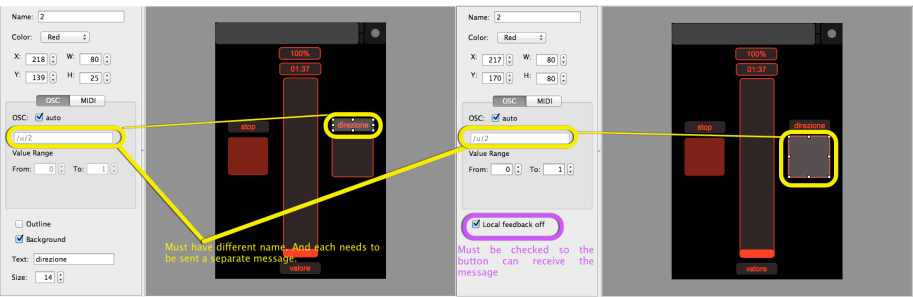
There are two mistakes in the Layout:
1. The label “direzione” and the toggle button for the direction both have the same TouchOSC address “/u/2” so the label receives the message sent by the sketch but not the button. If you change the address of the label to “/u/4” then the button will receive the message at OSC address “u/2”. You would then have to end a separate message to the label at OSC address “/u/4”
2. “local feedback off” in the button settings is unchecked. It must be checked as shown in the linked image for the button to receive the message.
In your code I changed
int val = LOW;toint val = 0;val = (boolean) msg.getFloat(0);toval = (int) msg.getFloat(0);Hope that helps!
From looking at saibailibero’s code, it appears he is connecting to an existing wifi network. I was wondering if this would work by putting the Wifi shield into adhoc networking mode and connecting the iPhone directly to the arduino.
I see in the OSCuino roadmap, they talk about wifi support being added this year, but being impatient, was hoping peer -to- peer iPhone -to- Arduino Wifi shield could be made to work now?
I see in your blog, you mention Wifi wasn’t possible, that’s why you chose the ethernet shield/router combination, but I can’t see why not Wifi shield only wouldn’t work. I must be missing something.
Hi Carl,
Yes, I may have said that in a post but that certainly an older post. There are WiFi solutions not involving a little pocket router that may work to some degree.
None of them are likely to come even close in performance to a W5200 based Ethernet shield in conjunction with a TP-Link TL WR703n pocket router. The Arduino WiFi shield is also substantially more expensive than the above mentioned solution.
The Router-W5200 combination also can be easily connected to directly as the Router comes out of the box in AP mode.
The Ethernet library also is very mature, thats not something that can necessarily be said about the current WiFi shield solutions.
The Oscuino library requires the Ethernet (EthernetUDP).
If the WiFi shield supports that than I see no reason that the WiFi shield should not work.
Whether you can connect to the WiFi shield in Ad-Hoc mode is another question that I cant answer. In the past the WiFi shield did not support Ad Hoc or AP mode. That may have changed by now.
hello
I’m in trouble in my sketch.
I can turn on and off the LED with touchosc on android. But when I leave the connected LED and closing the touchoc app and open again, the app loads with the off button!
is an error in programming or in the app?
Please can you help me?
#include
#include
#include
#include
byte mac[] = { 0x90, 0xA2, 0xDA, 0x0D, 0x83, 0xEA }; // Entre com o valor do MAC
IPAddress ip(192, 168, 0, 150);
byte gateway[] = { 192, 168, 0, 1 };
byte subnet[] = { 255, 255, 255, 0 };
EthernetServer server(80);
int serverPort = 8000;
int destPort = 9000;
int ledPin = 2;
int ledState = LOW;
int aa = 0;
EthernetUDP Udp;
void setup(){
Serial.begin(9600);
Serial.println(“OSC OK”);
Serial.println(ip);
Ethernet.begin(mac, ip);
Udp.begin(serverPort);
}
void loop(){
//process received messages
OSCMsgReceive();
}
void OSCMsgReceive(){
OSCMessage msgIN;
int size;
if((size = Udp.parsePacket())>0){
while(size–)
msgIN.fill(Udp.read());
if(!msgIN.hasError()){
msgIN.route(“/ard/ledverm”,toggle1);
}
}
}
void toggle1(OSCMessage &msg, int addrOffset){
ledState = (boolean) msg.getFloat(0);
OSCMessage msgOUT(“/ard/ledverm”);
aa = digitalRead(ledPin);
if (aa == 1) {
Serial.println(“TESTE!”);
}
digitalWrite(ledPin, ledState);
msgOUT.add(ledState);
if (ledState) {
Serial.println(“LED on”);
}
else {
Serial.println(“LED off”);
}
ledState = !ledState;
Udp.beginPacket(Udp.remoteIP(), destPort);
msgOUT.send(Udp);
Udp.endPacket();
msgOUT.empty();
}
Hi Carlos,
Why touchOSC on Android starts with the button “off” I cant answer but it really does not matter anyway. When you start TouchOSC it does to know the sate of the Arduino so it does not know if the LED on the Arduino is turned on, or off.
TouchOSC at the moment does not provide any feature that would automatically update it with the status of the device you are trying to remotely control – the Arduino in this case. You could add a button called “update” to your TouchOSC layout that sends an OSC message to the Arduino an then the Arduino would respond back with OSC messages that reflect the current status of the Arduino.
I would not call this a bug in TouchOSC but a feature that would be really nice to have. On iOS the Layout starts in the state I left it, so If I switched the LED on and started another app on my Phone in that case when TouchOSC comes back the Button is still on.
It’s very good project. so, If you don’t mind, I would like to introduce on WIZnet museum for everyone. WIZnet produce the W5100 on Ethernet shield. Hopefully, you will allow this. and one more thing to say, I have almost made a new W5500 Ethernet shield. if you have interest, then I could send free sample when it releases. just send your address to my email suhwan@wiznet.co.kr. I think, it is good for your future experiment :). Thanks.~
Hi Roy,
Yes, you may introduce the project to the WizNet museum. I am assuming you are referring to the ToucchOSC tutorial ?
Another thing I might mention is a feature that your W5100, W5200 and I am assuming the W5500 also have and that is the ability for multicasting. This is the one feature that allows to use ZeroConf networking and Bonjour which is Apples implementation of ZeroConf networking. I use this in my own LED lighting systems in conjunction with TouchOSC and it it works very nicely.
Hi Roy,
I’ve looked at a number of the posts/articles on your WizNet museum and let me make one thing clear.
Given what you’ve asked here and finding some hard evidence I highly doubt that all of these articles were written by WizNet employees. The article “WIZ820io and Micro SD Card adapter” is an exact copy of the same article from the PJRC website where it was originally posted.
In those articles on your website you have not credited the original creators of these articles and I find this highly objectionable.
Please consider crediting the original authors of these articles!
Hi Trippy Lighting, Wonder your real name is ….
Thanks so much for the amazing tutorial for beginner as I am.
I already tried and make some mods of your sketch to fit with my personal hobby project.
But since I am not a good coder, my sketch seems too long and not effecient.
Hardware
– Arduino Mega 2560 R3
– DFR0125 Ethernet Shield R2.0
– DFR0144 Relay Shield R1.2
iPhone App
– TouchOSC with Touch Editor
Objectives :
– Create 8 channels ON OFF Switch Control for Lamps
– Create 2 channels Analog Dimmer
Status of Project :
Since my order 8 Solid State Relay Module 8 Channel OMRON SSR G3MB-202P 250V 2A has not been arrived, I made dummies so that :
– Lighting Control 1 to 4 are controlling Relay 1 to 4
– Dimmer Value are dummies only
My full document project:
https://www.dropbox.com/s/fg3b5698a6kxl3p/Trippy%20Lighting.zip?dl=0
By reading my sketch, there are to many repetitives lines such as :
void L1Data(OSCMessage &msg, int)
{
LightingState = (boolean) msg.getFloat(0);
OSCMessage msgOUT(“/lighting/l1”);
digitalWrite(LightingL1, LightingState);
Udp.beginPacket(Udp.remoteIP(), IncomingPort);
msgOUT.send(Udp); // Sendback OSC message to TouchOSC
Udp.endPacket(); // Mark the end of the OSC Packet
msgOUT.empty(); // Free space occupied by message
}
There are 8 times similar function coding
and exact coding for about 10 times like this below :
Udp.beginPacket(Udp.remoteIP(), IncomingPort);
msgOUT.send(Udp); // Sendback OSC message to TouchOSC
Udp.endPacket(); // Mark the end of the OSC Packet
msgOUT.empty(); // Free space occupied by message
I hope you would like to give me suggestion regarding Programming Code how to optimized the codeing sketch and minimizing repetitivenes as it will consume memory and making instruction lags
Thank you so much in advance and regards,
Adrian Susianto
Sketch and TouchOSC updated
https://www.dropbox.com/s/fg3b5698a6kxl3p/Trippy%20Lighting.zip?dl=0
Features Added:
– Comments Added for sketch programming line explanation (hopefully I didn’t make any mistakes at the comments)
– Reset Button Function Added at far right bottom of TouchOSC display (small green button)
– Display Status added to indicate reset procedures are done and OK
Beside about how to optimized my codes, I have another questions:
1. Sometimes but many times Sending TouchOSC data from iPhone was failure and nothing happenned on the Arduino. For Example, I pressed Light1 button to turn ON the Lamp1, but manytimes it was failure and I have to several times pressed again. Why it happened and how to avoid that ?
2. How to reset the Fader so that after pressing the Reset Button, all fader back to far left position (position 0). I have made procedure to set fader to zero but the graphic TouchOSC won’t back to far left position in my iPhone
3. How to set the “Display OK” procedure at the beginning of program (just after uploading or resetting the Arduino device) ?
Thank you and best regards,
Adrian Susianto
Updated Sketch and TouchOSC
https://www.dropbox.com/s/km9ekxthy1on0wk/Simple%20Lighting%20Control.zip?dl=0
Board Layout

TouchOSC Design

Hi Adrian,
Thanks for the positive feedback.
Judging by your video this looks like a nicely executed project!
Dont worry about the quality of your code. That will get better as you gain confidence in your projects. Your code is very readable and excellently commented/documented and very neatly formatted.
To answer our questions:
To 1: I’ve had the same problem when I used my iPhone 4. I also sometimes had to use the buttons several times. However I also used ann iPad to control the same devices and never had this problem with the iPad. I also observed that it got worse with the iPhone when the batteries got empty.
I have upgraded to an iPhone 6 by now and also don’t have this problem anymore, so I believe this can attributed to a problem with the WiFi abilities of the iPhone 4.
To 2:
The fader does not jump back, because you’ve given it the same OSC address “/lighting/dimmer1” as the little “Data” label to the right of the fader. Each control in TouchOSC needs it’s own OSC address so for example name the the label “/lighting/label1” etc. then it should start to work.
To 3:
You basically have to add another ToouchOSC control button or use an existing one that when pressed will send an OSC message to the Arduino so the Arduino sends OSC messages to all of the controls on your TouchOSC layout. Unfortunately TouchOSC does not send a message when it is stated on any iDevice (or Android) that could be used to update screen settings automatically on startup of touchOSC.
To reduce the amount of code, even though it’s not really that much, you can generate a function for sending messages:
void msgSend(OSCMessage &msg){
//send the outgoing message
	if(msg.size()){						//if message size is not zero
		Udp.beginPacket(Udp.remoteIP(), IncomingPort);	//start UDP package
		msg.send(Udp);					//fill UDP package with OSC message
		Udp.endPacket();				//and send it
	}
	msg.empty();						//empty the message
}
And then call that function like so:
I hope that helps.
My real name is Peter 😉
Hi Peter..
Glad to know your real name, rather called you with Trippy Lighting hehehehe..
Btw how come you know that I come from indonesia ?
From IP address ?
Thank you for your fast reply, actually I am very helped from your tutorial blog, definitely answered my questions regarding TouchOSC with Ethernet Shield to control outside world.
Actually I made this project for my hobby and my curiosity about smart home automation and controlling everyday device from iPhone.
With the help of TouchOSC GUI which is more simple to design and implement compared with any other resource such as Ardumote, iArdunio Connect, etc.
What is your email address or maybe you have Whatsapp so we can easily keep in touch because I might have need your instruction a lot regarding multichannel dimmer.
I will discusses this dimmer in new a thread.
For now, I will follow your instruction regarding the Resetting Fader Control and try to make it work.
I will post the result.
By the way, my 8channel SSD and 8 channel Relay already arrived.
The next step is to replace my Relay Shield with these modules.
Thank you again and catch you soon..
Cheers,
Adrian Susianto
Added Video as Overview of this Project
That is a very nicely engineered demo setup.
Do you intend to take this to the next step and use a custom PCB with the Omron SSDs and perhaps make a small run of boards ?
I am not sure who’d be a good PCB supplier in your part of the world (Indonesia ?) however if you intend to make larger quantities than just a hand full I can recommend Hackvana.com. Mitch, the guy who runs this service is based in Australia, very knowledgable and has contact to factories right in Shenzsen, China. Ive ordered 100 boards from him for my LED shields and they were of excellent quality. Better than iTead for example.
If you do go the custom board route I’d recommend to use an Ethernet solution using the W5200 Ethernet chip instead of the W5100 on the Ethernet shield you have. The WIZ820io is for example $8 cheaper than the Ethernet shield you have, much smaller and has much better performance. If you are looking for a full Arduino compatible replacement that is much more powerful, much less expensive and much smaller with better technical support then look at the Teensy boards from pjrc.com.
Hello Peter..
Just received my Relay Modules and Solid State Relay Modules.
8 Channel OMRON SSR G3MB-202P 250V 2A

8 Channel Relay 250V 10A

Actually I have no further purpose to make it bulk production. Not yet.
Because I think many people already able to create this similar project so I think it would be not so much value for commercial.
So I intent this project as my anthusiasm and educational purposes only.
I realize also that I’m no good in programming klanguage so that I have to learn much.
But yes in the future when the project is already more complex, more stable, more functional and bugs already eliminated, I have planned to install in my house to show off my friends hahahaha.
Now since the SSR and Relay board already here, I have to remove the Relay Shield and start to re-program the pin used and make it more functional using dimmer. Multi channel AC Dimmers is the one that I have problem to implemented in Arduino using TouchOSC.
Will be need your assist for this one. But I will try my best first so I will learn something from you.
Is it okay to discuss it in your Blog ? Or better to use email ?
Thank you in advance.
Cheers,
Adrian Susianto
Sketch Updated
https://www.dropbox.com/s/cnxs74jf3oa5ims/Simple%20Lighting%20Control.zip?dl=0
Features Added
– Comments Added for sketch programming line explanation (hopefully I didn’t make any mistakes on every comments)
– Reset Button Function Added at far right bottom of TouchOSC display (small green button)
– Display Status added to indicate reset procedures are done and OK
– Display what and where Lighting Switch Status when tap
Hi there Peter,
// #HopefullyYouDidNotBoredWithMyMessages 🙂
I have managed to modify my Reset Procedures and Yes, I have mistaken for creating the same address for “Display Data Dimmer” and “Fader Dimmer” with the same label.
Now the sketch is done for this basic phase and all working well. reset already fix and done.
The next phase will be the creepy Dimmers he..he..he..he
But I have questions regarding my code for resetting the Fader.
In order to reset Fader, I have 2 steps which are:
1. Reset Fader to 0 or far left position
2. Reset Data Value Display to Zero
But When I create the code for the first time in one function it has error:
redeclaration of’OSCMessage msgOUT’
Why I can not use this OSCMessage msdOUT in a function, as you seen that I already Ended the sending UDP Message with:
Udp.beginPacket(Udp.remoteIP(), IncomingPort); // Prepare UDP Port with Message Data
msgOUT.send(Udp); // Send OSC message to TouchOSC
Udp.endPacket(); // Send End Message signature
msgOUT.empty(); // Set Free space occupied by message
before I call another “OSCMessage msdOUT(xx,yy);”
In that case I have to create another function just to reset the dimmer data display as follow
And there are more coding lines again
Thus I have also call this function in the Reset Procedure as follow :
Which are consuming more memory for repetitives function.
So actually what should I do for minimizing repetitive function like above ?
Thank you in advance,
Adrian Susianto
Hi Adrian,
You probably need to delve a little deeper into the object oriented programming aspect. You need to understand what classes and objects are.
OSCmessage is a class that describes the basic data structure for the OSC messages and it also defines the methods that will be used to work with the data in the Class.
What
OSCMessage msgOUT("/lighting/dimmer1");does is that it creates an object of the OSCmessage class with the name “msgOUT”. This is a container in a sense for the OSCmessage. Obviously you cannot have two containers with the same name 😉 The Object also contains the method to add message to the object. This is what
does.
If you want to reuse the object so send another message you first need to remove the old message, which is what
does.
This last line of code ins actually not necessary in your sketch. The reason for that is that all your OSCmessage objects are created locally in functions. Once the function completes and returns the object is destroyed and the memory it occupies is released anyway.
However, if you want yo re-use Objects you can define them globally before the setup(); section.
in that case you will have to empty them once the message is sent. In that case you would not have to create the object new for each function.
For now I would not worry about code efficiency (speed) or using too much memory. As Ive already mentioned most of the size of your code comes from the imported libraries, not from the code you wrote.
Good Morning, Peter
Thank you for the coding explanation.
Now I bit understand about OOP is, which I never learn into it.
But I can follow your instruction well, it clear enough for me.
Just also I understood from your reply, that if I use the function from the libraries, it won’t make further consuming memory because the functions I used are already declared in memory before, and what I did was just call that function. So no further new function was created. Hmmm yes, I just realized this one. Thanks for that.
So I won’t focus more in optimizing coding right now, but still try to make my coding easy to read and understandable easily.
Now I’m still in progress to make 1 functional dimmer first.
Ok Thank you so much Peter for all your effort, and have a nice weekend.
See you later
Just inform you that I use GitHub now, so whenever some missing links occured, you still got my documents here :
https://github.com/adriansusianto/iPhone-TouchOSC-Lighting-Control
Hello
I am doing automation in my house and I enjoyed your explanation … however there was an error in EthernetUdp.h library and I can not solve.
Can you help me?
If you let me know what error that was I can certainly try.
Missing ‘author’ from library in C:\Users\diego\OneDrive\Documentos\Arduino\libraries\arduino
Thanks so much for this.
It works great with TouchOSC.
However, I have tried to implement it using VDMX instead of TouchOsc, having VDMX generate/send the OSC messages. I can’t seem to get it to work, although I can’t see any reason why it wouldn’t. I suspect the issue has to do with the formatting of the OSC message out from VDMX. I am not sure how to send the same “header”.
For example, your .ino sketch is listening for osc messages that begin with “/OnOff/toggle1”, and or “/Fader/Value”.
When turning on OSC output for a fader in VDMX, the default OSC Msg Address is something like “/FromVDMX/x”.
I have tried changing the OSC Msg Address to:
“/Fader/Value”
“/Fader/x”
“/Fader/”
“/Fader”
“/x/Fader”
“/1/Fader”
etc… but I can’t seem to figure out what it SHOULD be for the .ino sketch to “see” it.
I have confirmed the proper i.p. address and ports are configured for the arduino on the network, and like I said, I can control the arduino fine using TouchOsc from my iphone on the same network.
I know you did not write this for VDMX, but might you, or anyone else out there have any clues?
Thanks again!
Hi Rob,
Good to hear that it works!
You could try to monitor the OSC data you send to a given IP address and port with this little app http://www.kasperkamperman.com/blog/osc-datamonitor/
It will require you to install allegory version os Java, but it maybe worth it.
Check it you and see if that helps you to see what VDMX is actually sending out.
I’d be glad to help out.
You read my mind! That is actually what I ended up doing prior to your response …and now it works with VDMX perfectly. Thanks again for your help and work on this!
Great.! Glad you got his to work as well. Before I discovered that little tool I modified the basic UDP receive sketch and just printed everything that came in on the Serial Monitor.
You wrote “Before I discovered that little tool I modified the basic UDP receive sketch and just printed everything that came in on the Serial Monitor.” How would one do that? I tried Serial.print( msgIN ); and Serial.print( OSCMessage msgIN ); , but I obviously don’t fully understand the way the upd msg is parsed. Any help greatly appreciated.
You can also use ESP8266. It works very well and it’s cheap.
Thanks for sharing!
Yes, that is true for the OSC part. If it is also true for the Bonjour part (which I still have not described) is another question. Very few of these ultra cheap WiFi modules support full multicast DNS, which is required for Bonjour to work. Most WiFi routers, including the TP-Link mini routers, however, do support mDNS and DNS-SD.
Hey Peter.
Thanks for the nice tutorial, it has helped me a lot.
I’m very close to controlling my LED-strips through touchOSC now, but I’m having a problem I don’t know how to fix.
I have a Teensy 3.2 with an ESP8266 breakout connected through serial.
The ESP receives UDP packets and sends them to the Teensy with SLIP.
I’ve taken your example and rewritten it a bit so that when a message is received and routed to either ‘ToggleOnOff()’ or ‘FuncValue()’ it will output the value or state of the LED to the serial that connects my PC and Teensy.
When I push the on/off button I get a response, and I also get a response from the slider. But the value is always 0. In other words ‘msg.getFloat(0)’ returns 0, and I don’t know why this is happening.
I have tried installing a program on my MAC to pick up UDP packets and have touchOSC send it’s messages to my computer IP and port.
It seems like the values contained in the messages from the fader are different as I slide the fader (in other words, not 0), but it’s not quite in human readable format so I don’t know exactly.
Next time I’m going to sit down with this I will for testing purposes skip the Teensy and just use the ESP in order to see if the ‘conversion’ from UDP to SLIP truncates the OSC messages.
Do you have any other tips for me maybe?
Good to hear that some of it is working. Did you change anything on the TouchOSC layout ?
Yes, but I had the same problem before I changed anything.
Yesterday I tried to skip the Teensy, like I wrote, and use only the ESP. This worked flawlessly. So it seems to me that somewhere in the process of taking UDP packets and then sending them from the ESP to Teensy over serial with SLIP the problem occurs.
This goes out of the scope of your tutorial, because your part of the code works great.
But if you’d like to have a look I’ve posted a more detailed explanation with all the code I use here:
https://forum.pjrc.com/threads/34640-OSC-message-value-always-0-after-sending-with-SLIP?p=105203&posted=1#post105203
I changed the line (I think it’s line 100 or thereabouts)
in void funcValue(OSCMessage &msg, int addrOffset )
int value = msg.getFloat(0);
to
float value = msg.getFloat(0);
The behaviour of the slider started working way better!
Before that it was either Max (1) or Min (0)
I also had to rename the controls in TouchOSC to match the code
“/OnOff/toggle1” and “/Fader/Value”
(unless I missed a few steps in the tutorial!)
Anyways…. great tutorial! Helped a lot!
Many of the Oscuino example programs won’t work for me – but this does!
Hello, I’m a Maxuino user who’s trying to use his minimal arduino skills to help his kid with some arduino OSC programming so please excuse if this is a dufus question… we’re trying to adapt your touchOSC sketch to read input from the TouchOSC xy controller (the square with the little puck in it). As I imagine you’re aware, TouchOSC sends two values (x,y) in addition to the controller name for the XY object. the data obviously isn’t being sent as a bundle because TouchOSC doesn’t send bundles, so we are wondering how to parse the incoming message in a way that will allow us to extract the individual x and y values. Any help will be much appreciated.
Hi Jonathan,
I apologize or the very late reply!
It should be very simple. If you look at the TouchOSC documentation for the XY pad you’ll see that it simply sends one more float value than a regular slider, which is the second control in my little tutorial.
Replacing :
int value = msg.getFloat(0);with:
int value_x = msg.getFloat(0);int value_y = msg.getFloat(1);
Should be all that is needed to get you access to the X and Y values the slider control in TouchOSC sends. If that explanation is not clear, please let me know and I’ll provide an functioning example layout for TouchOSC and Example sketch sometime over the weekend.
preciso de uma ajuda mano sobre esse app pode me ajuda ?
Unfortunately I don’t speak Spanish and trying to translate your last comment into English using Google translate was not very successful.
Hi,
First, thanks so much for the explanation of how to get the XY values. We are now able to send data from the XY object in TouchOSC and use it to control a little robot arm he built… very cool. The thing is, now he wants to try to do it wirelessly using a wifi shield. We are definitely arduino novices and I’m wondering if trying to substitute a wifi shield for the ethernet shield is going to involve significantly more advanced programming skills. Most of the simpler wifi examples we’ve found involve sending commands from a web browser and I have no idea if it’s even realistic to try to send OSC from a phone to the arduino via a wifi shield. (typical of my kid, he’s not interested in going with the simple solution of using a pocket router hardwired to the ethernet shield.)
Any advice?
Thanks!
On Thu, Aug 4, 2016 at 7:56 PM, Trippy Lighting wrote:
> trippylighting commented: “Hi Jonathan, I apologize or the very late > reply! It should be very simple. If you look at the TouchOSC documentation > for the XY pad you’ll see that it simply sends one more float value than a > regular slider, which is the second control in my little tutor” >
Him Jon, I like your Kid!!!
I am glad to her that you got it to work!
No, I don’t think that really requires any advanced programing skills, provided you pick the correct WiFi solution.
My recommendation would be to simply forget the Arduino Hardware. That goes for the actual Arduino board as well as for the horrible WiFi shield.
There are many Arduino compatible boards around and IMHO the best Arduino boards by far are produced by PJRC.com, a small Company in Oregon.
The sole proprietor Paul Stoffregen has committed many improvements to the Arduino IDE.
My suggestion would be to move to a Teensy LC or Teensy 3.1. Smaller, more powerful, less expensive. Even the Arduino libraries are better developed.
Maybe start with a Teensy LC for $11.65 (with pins) and add one of the available ESP8266 WiFi boards.
There is an adaption of the OSCuino library available for the ESC8266 boards in conjunction with the Teensy LC
A lot of the work is to initially figure out the correct connections and how to power both units. The Teesny LC can be powered directly from 5V USB power and has an on-board 3.3V voltage regulator. This ESP9266 module from Adafruit looks like just what you’d need.
All the above is fully Arduino compatible! I use the Teensy boards exclusively in my own products.
Thanks so much for your reply! Yeah, my kid’s pretty amazing… 13 years old, absolutely no coding experience as of a month ago and he’s already talking about unix shell commands and struggling to understand the bridge code for the Yun.
Unfortunately, it’s not getting us anywhere with our objective, which is to send UDP commands through a wifi connection. I have ordered a teensy 3.2 and the Adafruit Huzzah ESP8266. While waiting for them to arrive I started looking around for how to wire up the units. I confess to not having done an exhaustive search, but most of the stuff I read was pretty technical/confusing (and usually PC specific – I’m a Mac user) I don’t suppose you’d happen to have a link to something that would give me more of a “connect pin x to pin y sort of explanation (or an idea of how/where to look for it myself?)
Thanks again. I’m super grateful for your help (didn’t get much from the arduino forum) and can hopefully pay it forward at some point.
On Sun, Aug 28, 2016 at 3:47 PM, Trippy Lighting wrote:
> trippylighting commented: “Him Jon, I like your Kid!!! I am glad to her > that you got it to work! No, I don’t think that really requires any > advanced programing skills, provide you pick the correct WiFi solution. My > recommendation would be to simply forget the Arduino Hardware. Tha” >
Cancel my previous plea for help… at least for now. I found both a less expensive alternative to the Huzzah ESP8266 and a YouTube video that gives detailed instructions on how to hook it up. I’ll let you know how everything turns out!
Thanks!
Jon
On Sun, Aug 28, 2016 at 3:47 PM, Trippy Lighting wrote:
> trippylighting commented: “Him Jon, I like your Kid!!! I am glad to her > that you got it to work! No, I don’t think that really requires any > advanced programing skills, provide you pick the correct WiFi solution. My > recommendation would be to simply forget the Arduino Hardware. Tha” >
Just make sure that the voltage levels between the ESP board and the Teensy 3.2 are OK. The huzzah has it’s own voltage regulator on board, so you don’t need an external one. Just hook up to USB and start developing.
If you have question you’ll receive much more detailed help on the Teensy Forum.
And please keep me up to date on your progress!
In addition to the Huzzah, I picked up a couple of Diymall Esp-01 modules (at 6 bucks apiece) because I found a YouTube video that gave very specific instructions on how to hook them up (instructions for the Huzzah are less easy to find/understand) the ESP-01 doesn’t have a voltage regulator on it but I’m assuming that while we’re in the breadboarding phase I can power the ESP-01 with a 3.3 volt breadboard power supply (700mA)… yes?
Jon
On Mon, Aug 29, 2016 at 8:42 PM, Trippy Lighting wrote:
> trippylighting commented: “Just make sure that the voltage levels between > the ESP board and the Teensy 3.2 are OK. The huzzah has it’s own voltage > regulator on board, so you don’t need an external one. Just hook up to USB > and start developing. If you have question you’ll receive mu” >
Ola , vejo que vc sempre responde os comentarios , gostaria de uma ajuda com esse aplicativo , preciso de fazer o acionamento de 5 lampadas , tenho todos os componentes porem não consigo fazer o acionamento você pode me ajudar ?
Can this OSC libraries control dc motors without using processing?
Yes, TouchOSC and OSC can communicate directly with an Arduino Board without having to run processing on another computer.
hi, thank you for this wonderfull tutorial!
I have a little problem: I can’t ‘extract” the OSC value (of funcValue for example) in a global variable. It’s always equals to zero in the others functions…
I declare before the setup an Int, and inside the function “funcValue”:
int globalValue = value;
But if I use “globalValue” in the loop, after “OSCmessageReceive();” globalValue is always 0…
Maybe you have a solution?
Thanks
David
ps: excuse me for my poor english!
Your English is quite fine. Better than my French 😉
TouchOSC sends and receives only values of the type float. You may have to type cast these into int.
Was wondering if you might know why when I press the toggle button in TouchOSC my Uno receives the message but as soon as I release the toggle button it sends two off messages? Thanks.
I am not sure this is it, but in the TouchOSC Editor, when you configure the Toggle Button there is a check box called “Local feedback off”. This needs to be enabled.
Yes, I have this enabled. Thanks for the reply. I’m not sure where the problem might be. It would appear that TouchOSC might be sending multiple messages but by their own documentation, this is not by design. I setup a push button and output to the Serial:
void pushTap(OSCMessage &msg, int addrOffset){
int pushState = (boolean) msg.getFloat(0);
Serial.println(pushState);
}
When I press the button I get two 1’s and when I release I get two 0’s. So the function is getting called twice for each incoming message. I just can’t make heads or tails why this would be happening.
I may not have anything to do with this, but you are defining pushState as int but then typecast the result as a boolean, instead of int.
Well, for anybody that runs into this I found the problem. Within options in TouchOSC there is a setting labeled “Touch Messages (/z)”. This should be turned off. If its on, it doubles the messaging for some reason. Cheers.
Thanks for posting this back.
Is there an Arduino sketch to control a two dc motors robot with TouchOSC (forward,backward,left and right)?
Thanks,
Hi
I use this sketch but it s faild . I think it s à port problem. On arduino serial monitor my ethernet shield adress appear.
I canar contrôle led with my iPhone 5. I havé Osc touch app.
Help me please
Giloris
Hi
Can you help me to the program, the trippy lighting sketch failed on my imac. I follow the tutorial but i dont understand
Regards
Giloris
I could, but so far you have provide no information that would help me identify the problem. “failed on my imac” is not very descriptive.
What failed, the compilation ? the upload ?
Or does it upload and what fils then ?
I need muc hmore detail to help you sort this out.
.
hi
thank you for your help. sketch compilation is OK and uploading too. The problem is on serial monitor after my IP shield adress appear
OSC Test
Arduino IP adress 192.168.1.xx.
and after there is anything
On my ipad , i use osc touch app , i use layout OSC touch with red and green bar idem the tutorial , i use on/off button but there is anything on serial monitor !
How i can send you seen capture ?
Regards
The IP address you reeived and which is printed in the serial monitor ( 192.168.1.xx.) is not a valid IP address.
It should be 4 numbers such as 192.168.0.154 that will appear. hte exact numbers are different based on you network.
The script provides a method to use a fixed IP address instead of DHCP. You have to comment the DHCP patr and out-comment the non DHCP part of the sketch.
Hi
No the adress is 192.168.1.37
It s arduino shield ip
Regards
Can you ping it from your computer ? Opern the terminal and type : “ping 192.168.1.37” wihtout the quotation marks and see if you get a response.
Adress ping is ok
On Mac console
Hi
I follow exactly this
Tutorial but the résult is not ok
I Work on iMac
Could you help me ?
Regards
Port problem ?
8000 and 9000 ?
The code present here don’t work into Galileo, I don’t know why, but the value os OSC message is always zero, but I discovered how put to work. Here the code to print values of the Button and Fader. Thanks to share us the library and sorry my poor English.
#include
#include
#include
#include
// Enter a MAC address and IP address for your controller below.
// The IP address will be dependent on your local network:
byte mac[] = {
0xDE, 0xAD, 0xBE, 0xEF, 0xFE, 0xED };
IPAddress ip(192,168,2,177);
IPAddress remoteip(192,168,2,4);
int serverPort = 8000; //TouchOSC (incoming port)
int destPort = 9000; //TouchOSC (outgoing port)
int ledPin = 13; //pin 13 on Arduino Uno. Pin 6 on a Teensy++2
int ledState = LOW;
// buffers for receiving and sending data
//char packetBuffer[UDP_TX_PACKET_MAX_SIZE]; //buffer to hold incoming packet,
char ReplyBuffer[] = “/OnOff/toggle1”; // a string to send back
//Create UDP message object
EthernetUDP Udp;
void setup() {
// put your setup code here, to run once:
boolean ledState = 0;
Serial.begin(9600); //9600 for a “normal” Arduino board (Uno for example). 115200 for a Teensy ++2
Serial.println(“OSC test”);
// start the Ethernet connection:
// NOTE: Alternatively, you can assign a fixed IP to configure your
// Ethernet shield.
Ethernet.begin(mac, ip);
Udp.begin(serverPort);
//server.begin();
Serial.print(“server is at “);
Serial.println(Ethernet.localIP());
}
void loop() {
// put your main code here, to run repeatedly:
OSCMessage *msgIN = new OSCMessage();
// if there’s data available, read a packet
int packetSize = Udp.parsePacket();
if (packetSize > 0) {
Serial.print(“Received packet of size “);
Serial.println(packetSize);
unsigned char *packetBuffer = new unsigned char[packetSize];
// read the packet into packetBufffer
Udp.read(packetBuffer, packetSize);
msgIN->fill(packetBuffer,packetSize);
//PRINT
Serial.print(“Contents:”);
Serial.println(msgIN->getFloat(0));
Serial.println(msgIN->size());
char str[packetSize];
//Serial.println(msgIN->getString(0,str,packetSize));
Serial.println(msgIN->getAddress(str));
Serial.println(str);
//Serial.println(Udp.peek());
}
}
A while back (Feb 23,2016), in response to a comment I made about troubleshooting OSC messages, you wrote: “Great.! Glad you got his to work as well. Before I discovered that little tool I modified the basic UDP receive sketch and just printed everything that came in on the Serial Monitor.” … How would one do that? I tried Serial.print( msgIN ); and Serial.print( OSCMessage msgIN ); , but I obviously don’t fully understand the way the upd msg is parsed. Any help greatly appreciated.
And….Have you had any success using a multitoggle and Arduino? I am having a hard time understanding exactly what the message being received by the arduino is in the case of a 1×4 mutlitoggle (see above comment about troubleshooting incoming messages).
Hi.
On a similar project, I have OSC running on a Teensy 3.6 and a WIZ820io (using the adaptor board that sells together with the WIZ820 on teensy page). But now I want to add Bonjour/mDNS and downloaded TrippyLighting (https://github.com/TrippyLighting/EthernetBonjour) EthernetBonjour library which compiles successfully. (it is the only one that compiled successfuly, all other library seem to be out-dated as they make direct calls to WS5100). In my sketch I have:
EthernetBonjour.begin(“arduino”);
and later
int res = EthernetBonjour.addServiceRecord(“test._http”,
80,
MDNSServiceTCP);
(just for testing I switched a webserver example)
on this line (res is sometimes 1 (successful) and sometimes it hangs and will never return) no bonjour service is visible on BonjourBrowser (OSX application). I can see other devices but never my Teensy 3.6. I’m pretty sure it’s not my LAN network. Also, after the EthernetBonjour.begin(“arduino”) the hostname arduino.local cannot be resolved. The ip address given by the DHCP works and is pingable – so I guess it has to do something with multicast support?
Do you have a working sketch with a Teensy 3.6 and a WIZ820io with working Bonjour? Apart from the Bonjour, everything else works perfectly (using DHCP or static ip address). I can’t seem to find a better Bonjour library that is up-to-date other from the TrippyLighting one.
Could that be related to a Teensy 3.6 or is there another library that is “better”?
Any help would be appreciated.
Sorry, for the super late reply. Ive not had a chance to test this with the Teensy 36. and the later releases of Teensyuino.
Hello
I know this an old thread but I recently tried your code on Uno + Ethernet Shield2. I am pretty sure my setup works using the following.
#include // needed for Arduino versions later than 0018
#include
#include // UDP library from: bjoern@cs.stanford.edu 12/30/2008
So I replaced your code with above three lines and kept everything the same…. ie. #include . The program does not work.
Any help is greatly appreciated…
Output
Opening port
Port open
VMDPV_1|1?U?AY5
OSC test
Printing Ip
0.0.0.0, port 0
—————————————
Code updated ——————-
void setup() {
Serial.begin(9600); //9600 for a “normal” Arduino board (Uno for example). 115200 for a Teensy ++2
Serial.println(“OSC test”);
Ethernet.begin(mac, ip);
if (Udp.begin(serverPort) == false) {
Serial.println(“\nUDP Connection failed”);
while (true);
}
else {
Serial.println(“\nPrinting Ip\n”);
IPAddress remote = Udp.remoteIP();
for (int i = 0; i < 4; i++) {
Serial.print(remote[i], DEC);
if (i < 3) {
Serial.print(".");
}
}
Serial.print(", port ");
Serial.println(Udp.remotePort());
}
}
html remove the tags angled bracket tags… here it is again
#include SPI.h
#include Ethernet2.h
#include EthernetUdp2.h
And what exactly does “does not work”mean ? Do you get any compilation errors etc. ? Any symptoms you see ?
Could you take a look at this?
https://m.imgur.com/gallery/xndCRKR
That link does not work
Hi Peter,
Looks like my last post didn’t go through. I have a work project I’m stuck on and your site and code has been the only thing that has been helpful. I’m using the code in the void setup to establish a connection on my network, and I’ve composed my entire OSCMessage with the little I’ve been able to learn from this site and the OSCuino documentation. I’m attempting to send a message from the
Hoping you might see this and be able to help in any way. Thanks so much for the informative site!
Below is the OSC message. Void setup and everything above it is same as your code and worked fine when I tested it with TouchOSC, per your tutorial:
OSCMessage msg("/1/toggle2"); msg.add(1.0); Udp.beginPacket(Udp.remoteIP(), destPort); msg.send(Udp); // send the bytes Udp.endPacket(); // mark the end of the OSC Packet msg.empty(); // free space occupied by message delay(1000);Oh whoops. When I posted this I now see the “awaiting moderation”. Apologies for the double post. 🙂
Hi,
Would this also work out of the box for communication between Arduino and OSCBridge, the software TouchOSC is meant to connect to so as to relay MIDI message to a DAW. If not, what should be modified?
Same question with cheap ESP8266 and ESP32 modules connected to an Arduino instead of TP-link routers.
Best,
S.
Pingback: TouchOSC Arduino Tutorial | trippy lighting
Pingback: Weather meter on iPad | macsbug