Author Archives: trippylighting

It’s been a while…

It is always a challenge to balance work and family life with demanding hobbies/passions and sometimes some things just simply have to wait.  This blog falls into that category. However, a number of things have been accomplished and I will update the blog over the coming weeks.

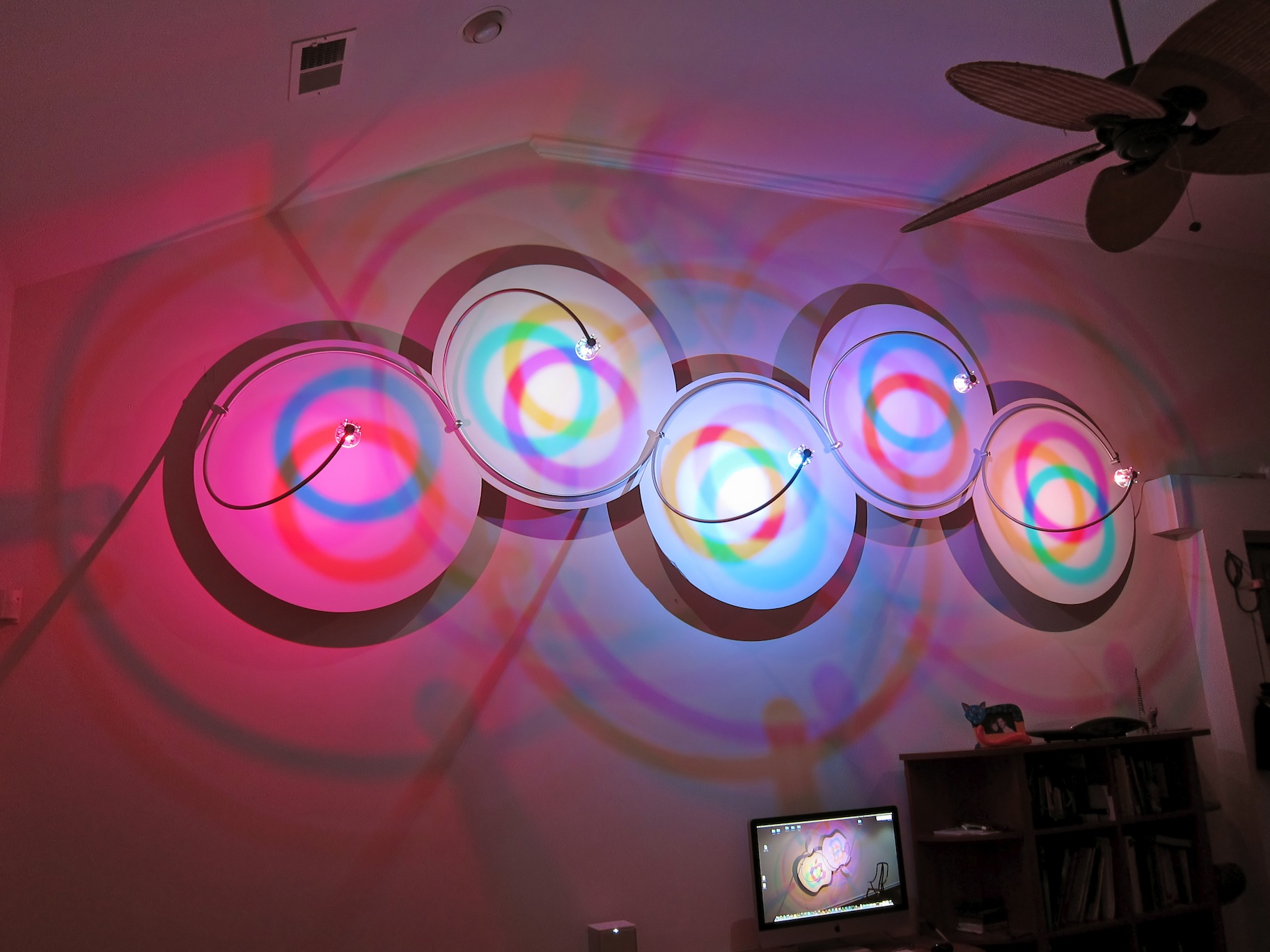
When I started this blog the lighting system in the first post was really just a feasibility study. Functioning, yet lacking in so many ways. While the visible mechanical part looks fairly finished  most of the deficiencies were in the electronics and software that are hidden behind the system. A typical hacker project in an early prototype state. Nothing that one could repeatedly build with any confidence. However, over the past year I have significantly upgraded the electronics hardware and software. While doing so I have learned many things that would have been impossible without the existence of open source hardware and software tools.

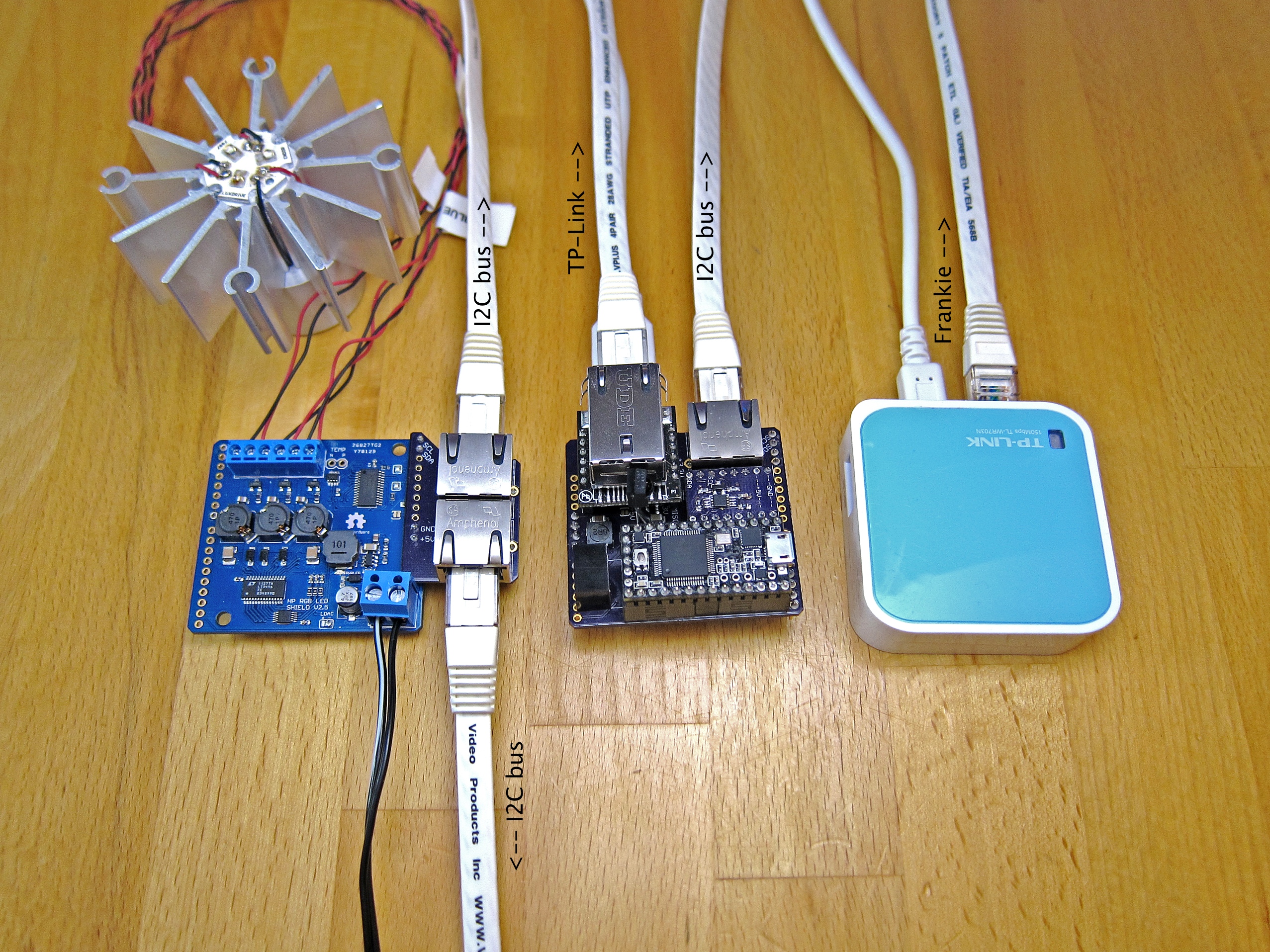
As many beginners do I initially used an Arduino Uno board and the Arduino IDE. However when trying to incorporate more software functionality into the project such as ZeroConf Networking/Bonjour functionality the memory of the Arduino became insufficient and I discovered the Teensy boards. At first the I used a Teensy++2 but a few months after I ordered it the Maker introduced a new Teensy 3 through a Kickstarter Project, which is now the basis for future lighting systems and other projects.

As the software became more involved I really had to brush up on my programming skills and needed to get a better understanding of the concept of object oriented programming and C++. The Arduino IDE also does not offer much functionality and I found the Eclipse Arduino IDE that allowed to program Arduino boards using the Eclipse IDE. At the time it did not accommodate the Teensy boards, so I contacted Paul Stoffregen the maker of the Teensy Boards and Jantje the Author of the  Eclispe Arduino Plugin and asked if they could imagine getting the Teensy boards integrated into the Eclipse Arduino IDE. To my surprise both jumped at the opportunity and got to work instantly. Getting the Teensy++2 to work took them less than a Month, but the Teensy 3 was a hard nut to crack. Particularly as Jantje did not own one. I could not really contribute to the software effort other than beta testing but I had two Teensy 3 from the Kickstarter reward, so I sent Jantje one of them.  After a few month the Teensy 3 and now also the Teensy 3.1 can be programmed using the Eclipse Arduino plugin and the new Eclipse Arduino IDE. The instructions of how to get that to work are here under the “Teesny, Arduino, etc.” tab.

As I had upgraded the hardware, the software itself also needed some upgrades to accommodate the new hardware. The Teensy 3 is fully Arduino compatible and worked right way, but my choice of Ethernet Hardware required some changes to the code.  The original Ethernet Shield I used in conjunction with the Arduino Uno hosts a W5100 embedded Ethernet chip and is supported by the Arduino Ethernet library. However the WIZ820io, which is much more capable, much smaller and cheaper than the Ethernet Shield but uses the newer W5200 chip.  This required a few changes to the Ethernet Library. Much more involved was getting the original EthernetBonjour library to work. It used direct access to the W5100 chip through the SPI library and it took a while to get it to work. It also duplicated some of the functionality of the Ethernet library. When the Teesnyduino Ethernet library was upgraded with code to automatically detect which Ethernet chip was used I would have had to adapt the EthernetBonjour library yet again. So I decided to completely overhaul the Ethernet Bonjour library and remove the immediate hardware dependance of it by removing all the direct hardware calls with calls from the EthernetUDP library. I hope that will eliminate the need for having to modify and adapt this library every time either the original Arduino Ethernet library or the Teensyduino Ethernet library undergo changes. It will also make it much, much easier to adapt it to use with new Ethernet hardware, e.g the CC3000 from Texas Instruments.

One of my goals was to be able to remote control the lighting systems from an iPhone. There were two promising iPhone applications available, Ardumote and TouchOSC. Ardumote allowed to send and receive simple commands through the UDP protocol. On my early Arduino Uno prototype using an Asyclabs WiShiled I also got this to work, however, it became clear that ArduMotes  iPhone user interface while visually very attractive would not allow me to create the functionality I had in mind. So I investigated how to get this to work with TouchOSC. The first obstacle was the library that shipped with the Asynclabs WiShield as it was difficult to work with. The only Arduino library that I could find for OSC was Recotana’s ArdOSC. Unfortunately this Library depended on the Ethernet Library, which in turn required the Ethernet Shield. No WiFi. Bummer! It took several month and a lucky find of a youtube video  that demonstrated Arduino WiFi functionality by means of a small Pocket WiFi router connected to the Ethernet Shield. Still today I believe this is the best and most reliable way to get WiFi to work on an Arduino. It is really dead simple! This allowed me to use ArdOSC and with some programming effort I was able  to remotely control the system through TouchOSC from my Phone via WiFi.

ArdOSC is not maintained anymore but in the meantime the inventors of the OSC protocol at CNMAT have released their own Arduino OSC library called OSCuino. I have replaced ArdOSC with OSCuino in my projects and hope to post a tutorial in the coming weeks on how to get that to work with TouchOSC. The idea is to develop a little demo application that will use Bonjour and OSC in conjunction with TouchOSC. I just have to figure out how to format/post code on WordPress.com :\ One would assume that that would be natively supported through a plugin by such a popular blogging platform but I find the editor disappointingly rudimentary!!!

Waiting for components…

Actually, most of the components are in already. A small shipment from Mouser will arrive soon and I still have enough conductors to build 20  shields. More are on order and will here within 2-3 weeks.  As with the ones needed for the prototypes I have not been able to find these at any source her in the US so I sourced them again  from the UK through Allied Electronics / RS components.

I’ve also decided to invest in a laser-cut stainless steel stencil from Stencils Unlimited. The mylar stencil from Pololu.com was fine for the prototypes and likely would have lasted a good number of boards longer but the print quality of a stainless steel stencil is simply better and more consistent. Also of course a SS stencil is much more durable.

Another project I have been working on is a micro controller project  with the aim to have “something” that can take advantage of the capabilities of this LED shield. One of the unique features of this shield is that it is controlled through the I2C bus. All components on the LED shield (with the Exception of the temperature sensor) are FM+ capable. The FM+ specification allows I2C bus frequencies of up to 1MHz. Instead of 3mA FM+ components can drive 30mA, which allows much longer connections between I2C components. On the other hand most normal Arduino’s allow max 400KHz.  So here is the Frankenduino I’ve described in a previous post:

IMG_2379_small

It features an I2C bus extender based on the PCA9600 chip from NXP. I’ve successfully used a shield on 5 meters of CAT5 Ethernet cable and on my oscilloscope signals looked crisp even at 1.5MHz, so there is quite a bit of headroom to use even longer cables and more devices such as the shield.

Also, what can’t be seen on the Photo is a IR receiver and the Teensy3 happily receives and decodes IR signals from my Apple Aluminum remotes.  A nice feature of the Apple remotes is that they can be paired to a device. I have not quite yet finished the code but I have determined the codes that the remote uses to be paired. However,  before I do that I need to make a second prototype, which features an SD card slot for permanent data storage. It would not make much sense to having to re-pair a remote every time the micro controller has been powered down.

In order to function together with the I2C bus extender I also re-designed the little Arduino I2C extender board. It has SMD pads for different pull-up resistors and also needs a small Schottky diode when operated in conjunction with the PCA9600 I2C bus extender. Below is a picture of a “complete” system, including a micro controller, WiFi Ethernet Hub for remote control ability through OSC / TouchOSC  and a LED shield with the I2C extension board. More shields can simply be daisy chained onto each other using inexpensive pre-configured CAT5 Ethernet cable.

IMG_2392_small

Another interesting idea I had is that it could be quite useful to expose all the functions of the LED shield through the OSC protocol. That way you could create LED effects code directly from a computer e.g. with MaxMSP or Pure Data without having to program the micro controller.

What’s next…

That is a question I’ve been contemplating about for the last few days. Having produced a first functioning prototype is quite encouraging! The question is now what to do with that success.

While there have been some people that have shown interest in buying one, currently the number possible orders does not exceed 20. That on the other hand would not justify having   50+ boards manufactured as that would include having to lay out about $2000 in advance. We have been in contact with a manufacturer in Germany (where the co-host of this blog is located) , specialized in manufacturing small series. This by the way is not a garage shop but a company that has been doing this for 20+ years and they’d be providing us with a complete turnkey solution. We send them the layout and money and they send us back completed boards. However, that only makes sense if the number of boards is larger than 50 for the first batch and would also really only make sense if there would be several batches of 50+ boards after that.

We could investigate to find a less costly alternative, however, the reduction in cost would have to be rather significant 30%-50% to really make a difference. We have a costed BOM and the price of all the components assuming Newark as the source of supply is about $27 for a qty of 50 boards. That does not leave much room for the labor to actually build the board.

My current thinking is to set up a fund raiser at Tindie and then post on a few forums to determine if there is enough interest to justify having 50+ boards manufactured. Another option would be InMojo. They are also offering assembly and serve as a sales platform for open source hardware.

Meanwhile, as I’ve mentioned above, my early success is really encouraging. Should there not be enough interest I can imagine making these myself depending on what QTY is involved. Making the first prototype was my first venture into SMD and Solder Paste and Reflow Soldering in a Toaster Oven. I started around 6:00PM in the evening getting all the materials ready, building a makeshift stenciling fixture etc. I was done with testing the prototype and had written the blog post by 11:00 PM. I believe it took me a good 120 minutes to populate the board. I had not made an assembly plan and I was doing it on my computer desk going back and forth between the layout and schematic in Eagle to see where the component went and and then I had to use the BOM with the Newark part number and find the bag/reel/tape with the component, and get them out of the packaging  to be finally be able to place the thing on the board.

With some better preparation and a little hardware I believe I should be able to get it to well under 30 minutes per board. I have ordered several of these and several of these and with some intelligent, labeling and an assembly plan things should progress much faster.

I have sets for 4 more prototype boards and will see how quickly these can be assembled with better planning within the next week or so.

Once that is completed I intend to send one or more to my partner-in-crime in Germany to do some testing under load. I don’t have enough LEDs to test the thermal side of things and he has managed to burn out one shield already. This should tell us how many LEDs the shield really can sustain! I only use one RGB LED @700mA per shield in my own lighting projects (trippylighting.com) and none of the thermal considerations are of any concern 😉

The things you can do with a Toaster Oven

After finally being able to source the Inductors from RS components in the UK I had thought that I was ready to go, as I had already placed an order for the solder paste. But I received a call from the rep and the particular brand and type I had selected was not available or recommended so I had to wait another 10 days until a better alternative was back in stock. So after having to wait another two weeks, yesterday evening UPS made the final delivery.

It is usually not a good idea to start new endeavors such as populating an SMD board with almost 50 components for the first time and reflow soldering in a hacked toaster oven for the first time at 6:00PM in the evening, after a full day of work with another one coming up the next day, but I had been almost giddy with anticipation and just could not help myself!

I re-stenciled the solder paste twice as I was not happy with my first two attempts. However, it turned out to be easier than I had thought. Then I started placing the first components on the board. Reflowed on the board the smallest resistors and capacitors look at least 50% bigger than they actually are. And while placing these was not easy and somewhat time consuming, the surface tension of the melted solder pulled these into the correct position. One of the big ICs fell onto its spot less than ideally positioned and the nicely stenciled solder paste spots were very smudged after repositioning the component. This did not look so good! But I was to curious about the reflow solder process, so I continued to populate the board.

When I finally was ready to place the thing in the modified toaster oven I fully expected it not to work. The reflow process is actually quite fast – somewhere around 4-6 minutes – for lead free ROHS compliant solder and I watched the process with eagle eyes.

For the first 3-4 minutes of pre-heating and soaking nothing happens visually, but when the systems goes into the reflow temperature zone one can see the solder getting shiny and flowing and you can see the small components reposition themselves. This looked surprisingly good and my outlook changed from No-way-Jose to “hey, this may actually work”

Reflowing this not so simple board with almost 50 components and several several fine pitch ICs worked great right the first time. I attribute that to the following three things:

  1. I did not get the cheapest available equipment but bought things that required little hacking and had proven to be successful. After all, I was not looking for yet another side project but an inexpensive but functioning solution. So I bought the reflow Oven Controller Shield and a Panasonic IR toaster oven that someone on the RocketScream forum had reported successful results with. I also made sure I bought the recommended K-Type thermocouple. 
  2. I followed the set-up instructions for the Arduino Reflow Oven Controller Shield and attached to and placed the tip of the thermocouple on a PC board that I placed in the reflow oven with the board to be reflowed.
  3. I paid attention to the Reflow profile of the solder paste I chose (Amtech NC-560-LF). The the heating part of the profile did not need much attention. If the oven has enough wattage it will heat up quickly enough and the PID control characteristics of the reflow Shield followed it precisely. I had copied and pasted the serial output into a spreadsheed and saw that the cooling, however, was much slower than recommended. Anyone who has ever had material sciences in school/college knows that the cooling of molten metal is as important to the proper crystallization of the solder joint as the heating is for activating the flux (etc.) so I made sure that I opened the oven door to get to the correct cool down speed -2-4 degrees celsius.

But of course just because  the board was nicely soldered still does not mean that it’ll work. And it did not in the first attempt as the power LED remained unlit. When placing the components I had switched the polarity of the one diode in the switched on-board power supply but this was an easy to detect mistake and because the diode was one of the bigger components it was easy to fix with a soldering iron.

So here it is, the first functioning prototype:

Image 


LED drivers – Update

When you start building objects like these lighting systems there are things that you don’t make yourself but which you buy, like aluminum tubing or the microprocessor board that runs the show. I also bought the LED driver boards that allow for the smooth blending of colors. These were designed by another hobbyist and he had a blog set up through which these could be purchased.

Last year when I was ready to build a second model I had hoped to contact him again for another set of these wonderful devices, but I discovered much to my dismay that he had apparently abandoned his blog as he had not responded to any questions or inquiries on his blog.

Fortunately he published the designs of his high brightness LED driver board as open source/open hardware and for the last several months I’ve been working on redesigning the board. While the final PCBs are not likely to come from ITEAD studio in China, this it what is show in the image below. Pretty nice for the price if you ask me! 10 boards for little more $50. The photo makes these look huge but in reality they are about 2″ x 2″. I am still waiting for the Inductors to come in from the UK (were not available in the US) and I should have assembled and functional prototypes within the next 3-4 weeks. My PID controlled Toaster oven is already set up and tuned to follow a temperature profile and I am feverishly waiting for the last components and the solder paste (lead free) to arrive.

For more details on these please follow this link http://ledshield.wordpress.com

Image

‘nother blog…

Life is interesting sometimes!

When I started this, after quite some research I discovered these LED driver boards that are controlled entirely by means of the I2C bus. These were designed and offered for purchase by another hobbyist and I bought 6 of them. 5 for the project and one as backup and for testing. I acquired these through his blog neuroelec.com and hoped that I would be able to do so again for the next project.

Unfortunately it seems that he has abandoned his blog, however, it being an open source and open hardware project, another user pulled over much of the information into another blog so as not to loose it and invited me to co-host the blog https://ledshield.wordpress.com.

I have mostly completed a redesign of the board with a few small improvements. We intend to get 50 of these manufactured as some people have voiced interest in this product and then I will be able to continue on my next lighting system project.

Lord Of The Rings

This is a rather shabby video taken with my iPad and posted directly from it. Of course I forgot to strip the audio track with the aquarium in the background but I doubt I can do that when posing directly to youtube from the from the iPad. Perhaps that provides it with some authenticity. No polished computer graphics here 😉

Now, after I have looked at the YouTube video myself I must say that the quality of the video on my iPad while still not great, is a lot better than the YouTube video. The Youtube conversion adds quite an amount of compression artifacts. When looking at the video even on the iPad it is quite clear, however, that there is some interference between the PWM control that fades the LEDs and the recording frequency of the image sensor in the iPad. Also, of course the camera software dynamically adjust the white point etc.

In combination of all these effect the video looks a little choppy. In person the fading effect is very smooth!

Steve’s Apples

Last Friday was a memorable day as it marks the one year anniversary of Steve Job’s passing. This did not occur to me until Saturday, when I finally decided, after having clicked past it several times, to see why my home page (which usually brings me to the Apple site) was different this time.
Of course it was still the Apple home page, however, it was temporarily changed to play a video with some of Steve Job’s memorable moments.

So I decided to slightly change my weekend plans and have a little creative fun with the Apple logo and use it in one of my lighting systems and decided to make a little concept rendering. Modeled in Blender and rendered with Indigo Renderer.

20121009-064735.jpg

Colorful LED lighting systems

Some time in the summer of 2011I started developing and building the LED lighting systems that will the main subject of this blog.
I use a host of software tools to develop these. For the mechanical parts of these systems I use Alibre Design Pro and Eagle for PCB development. Not enough good can be said about the wonderful open source hard and software world of Arduino embedded microcontrollers. Without these this would not have been possible. To visualize my ideas before I build an actual prototype the open software 3D graphics suite Blender and the unbiased render engine Indigo Renderer have proven to be invaluable. The banner on the front page for example is not a photograph but a computer generated rendering.

Now, having just said that, someone could just suspect that all the imagery on this blog is computer generated, so here is a real photo of the LED lighting system shown in the banner graphics. I took the photo with my iPad just before I sat down to write this first blog. The photo is amateurish enough that there is no mistaking it is a photo of the real thing 😉

IMG_2203_filtered